
Introduction#
This series of articles demonstrates how to use multiple ESP32-C6 peripherals to build a complete motor control and sensing system. We’ll explore:
- Motor Control PWM (MCPWM) for DC motor speed control
- Quadrature encoder (pulse counter) for motor speed measurement
- ADC for real-time potentiometer position reading
- Inertial Measurement Unit (IMU) via I2C for vibration analysis
- Wireless connectivity for data acquisition and processing
The goal is to build a comprehensive motor control and sensing system using the NuttX RTOS. We’ll implement open-loop speed control while measuring mechanical vibrations through an IMU. The system will stream sensor data wirelessly to a computer for logging and analysis, showcasing NuttX’s real-time capabilities, multi-threading support and the ESP32-C6 wireless connectivity features.
In this first article, we’ll focus on implementing basic motor control. You’ll learn how to use the ESP32-C6 MCPWM peripheral to drive a DC motor through an H-bridge, with speed control provided by a potentiometer input and reading the quadrature encoder. This will give us the basic functionalities before we can get to data offloading and analysis in the next article.
Getting Started#
If you are not familiar with NuttX, please refer to the NuttX official documentation and Getting Started with NuttX and ESP32 article. This article assumes basic familiarity with the NuttX environment and jumps straight into the application development.
As the starting point for our project, we create an empty repository that will be used as an extension of nuttx-apps. This approach allows simple integration with the NuttX build system, just like a standard application.
Hardware Requirements#
The following components are used in this project:
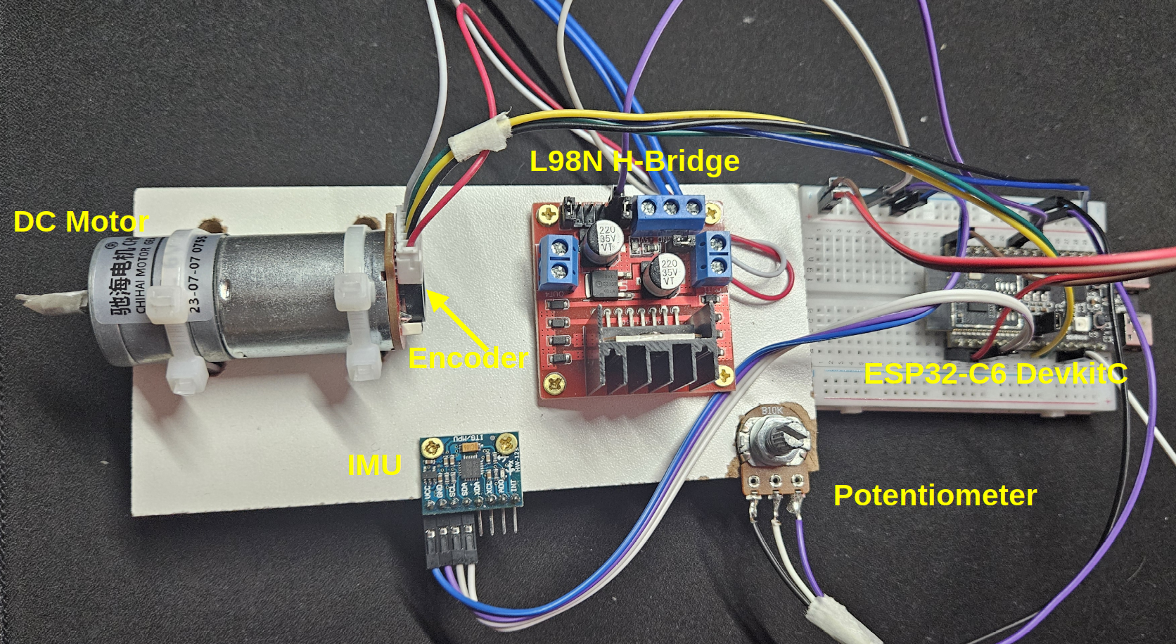
- CHR-GM25-370 6V DC Motor with integrated gearbox and quadrature encoder
- L298N H-Bridge motor driver module
- 10kΩ linear potentiometer
- GY521 IMU module (MPU6050)
- ESP32-C6-DevkitC development board
All components have been mounted on a test bench as shown below:
Motor Setup#
For motor control using the H-Bridge, we can use either one or two pins for PWM signals. Using one pin works but the motor will only spin in one direction, while two pins allows us to control both direction (forward and reverse) and speed.
While NuttX and the Espressif MCPWM driver support both modes, this application focuses on unidirectional control using a single GPIO. We’ll use PWM_A on GPIO 20 of the ESP32-C6 to control motor speed.
Our setup uses an L298N H-Bridge module driving a 6V DC motor. The motor includes a gearbox that reduces the output speed to 210 RPM. A quadrature encoder attached to the gearbox shaft will be used for speed measurement. The encoder is powered with 3.3 V and channels 1 and 2 of the encoder are connected to GPIO pins 10 and 11.
Potentiometer Setup#
Motor speed control is implemented using a normalized range from 0.0 to 1.0. A potentiometer provides manual control over this range, allowing intuitive speed adjustment.
The ADC support in ESP32 and NuttX makes this implementation straightforward. We’ll connect the potentiometer’s wiper to GPIO 3 (ADC1 Channel 3) and power it with the board’s 3.3V supply.
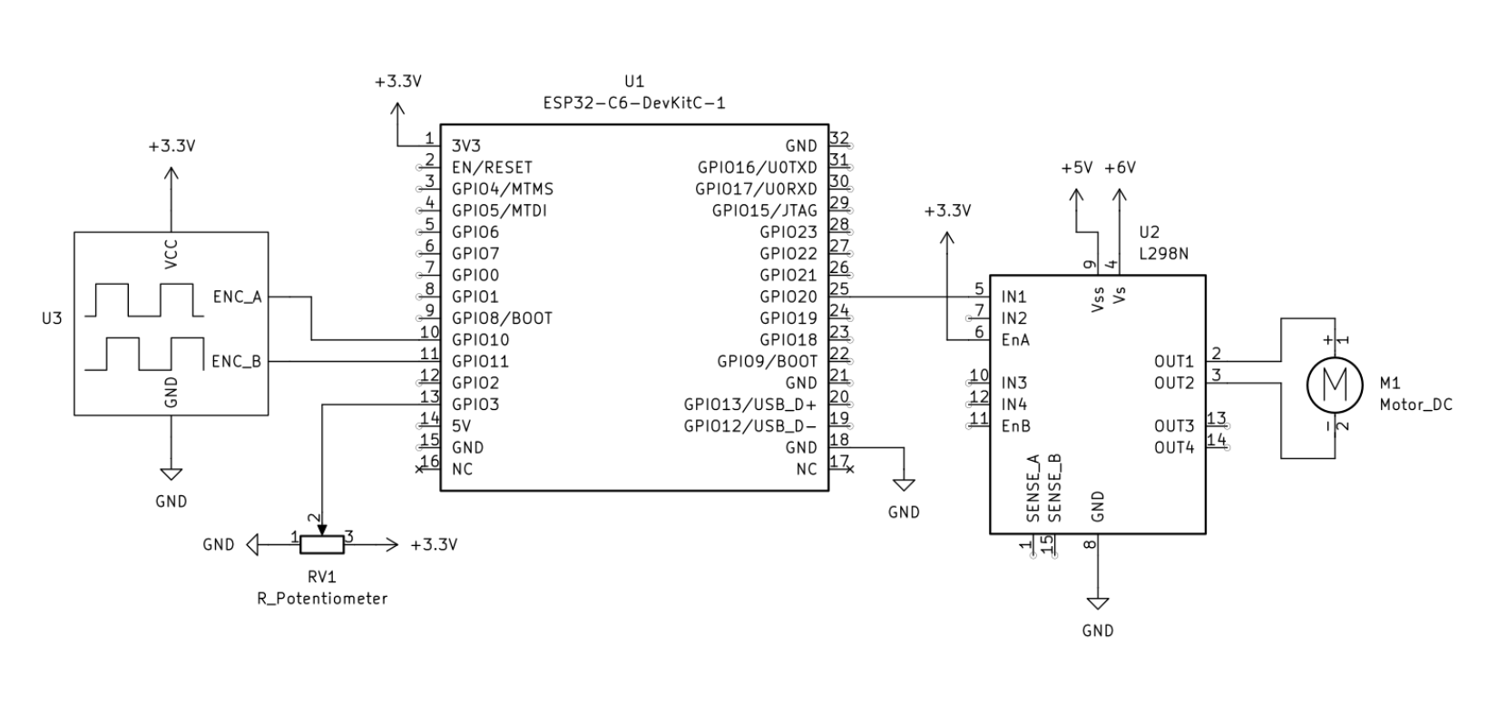
Schematic#
The schematic for this setup is available in the figure below.
Application Setup#
Before diving into the code, we need to configure the required drivers for motor control and ADC functionality.
We’ll start with the motor defconfig for the ESP32-C6, which provides the baseline configuration for motor control features.
Set up Motor Driver#
In the nuttx directory, configure the board using:
./tools/configure.sh esp32c6-devkitc:motor
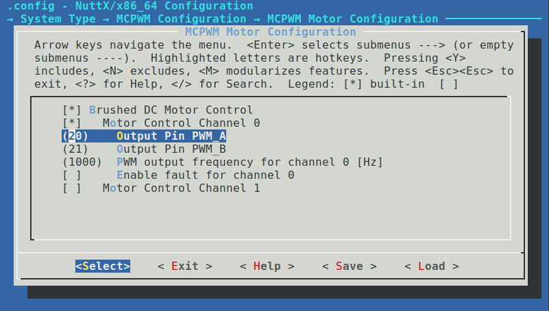
Next, enter the menuconfig interface with make menuconfig and navigate to System Type → MCPWM Configuration → MCPWM Motor Configuration. Here you can verify that GPIO 20 is correctly assigned to PWM_A output. This menu also allows customization of the PWM frequency and configuration of a fault GPIO pin, which can be used as a hardware safety cutoff.
Set up Quadrature Encoder#
The pulse counter (PCNT) peripheral of the ESP32-C6 can be configured as a quadrature encoder interface. While we could use the existing qencoder defconfig, we’ll configure it manually to understand the available options and their impact on encoder operation.
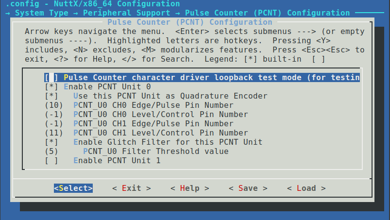
In menuconfig, navigate to System Type → Peripheral Support and enable Pulse Counter (PCNT / QE) Module. This will open a configuration menu where we need to set:
Enable PCNT Unit 0Use this PCNT Unit as Quadrature EncoderEnable Glitch Filter for this PCNT Unit
The quadrature encoder driver operates in X4 mode by default, providing maximum resolution for position and speed measurement. Configure the GPIO pins as follows:
PCNT Unit 0 Configuration:
- CH0 Edge/Pulse Pin:   GPIO 10
- CH0 Level/Control:    GPIO 11
- CH1 Edge/Pulse Pin:   GPIO 10
- CH1 Level/Control:    GPIO 11
Finally, enable the generic quadrature encoder driver support:
- Navigate to
Device Drivers - Enable
Sensor Device Support - Enter the Sensor menu and enable
Qencoder
Once configured, the quadrature encoder will be available as a character device at /dev/qe0.
Set up ADC#
With its 12-bit SAR ADC, the ESP32-C6 can directly read the potentiometer position. Although NuttX provides a ready-to-use adc defconfig, following the manual configuration steps helps understand how the ADC peripheral is set up for our specific application.
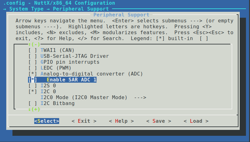
In menuconfig, navigate to System Type → Peripheral Support and enable the ADC driver. The ESP32-C6 provides one ADC unit, while some other ESP32 variants offer two units.
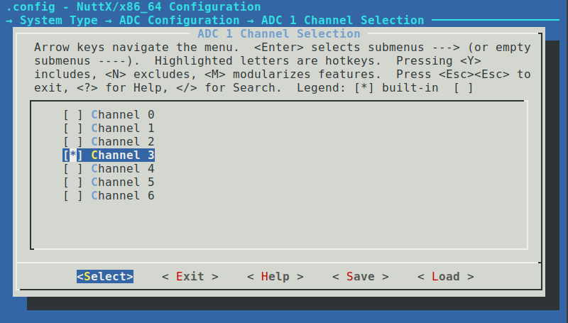
Under System Type → ADC Configuration, you can configure the ADC’s input attenuation, operation mode, and channel selection. Navigate to ADC1 Channel Selection and enable ADC Channel 3 (GPIO 3).
Each ADC channel maps to a specific GPIO pin. You can find these mappings in the ESP32-C6 datasheet or the NuttX documentation for ADC.
For debugging purposes, it’s recommended to enable the ADC example application. Navigate to Application Configuration → Examples and enable ADC Example along with Use software trigger.
Verify Driver Registration#
After configuring the device drivers on menuconfig, let’s verify they’re properly registered in the system. Build and flash the firmware:
make
make flash ESPTOOL_BINDIR=./ ESPTOOL_PORT=/dev/ttyUSB0
Open a serial terminal and check the available devices:
nsh> ls /dev
/dev:
 adc0
 console
 motor0
 null
 pcnt0
 qe0
 random
 ttyS0
 zero
Success! We can see /dev/adc0, /dev/motor0 and /dev/qe0 are now available, confirming successful driver initialization.
Save Configuration#
It’s a good practice to save working configurations for future use. This eliminates the need to manually reconfigure menuconfig options each time you rebuild.
Save your current configuration:
make savedefconfig
Make sure to copy the generated defconfig file outside the nuttx tree to prevent it from being deleted during make distclean operations.
Writing Application Code#
Our motor control application implements the following functionality:
- Opening character driver for motor and ADC
- Motor speed control using a normalized range (0.0 to 1.0)
- Emergency motor stop capability
- ADC sampling from the potentiometer
- Real-time conversion of ADC readings to motor speed values
- Continuous speed updates based on potentiometer position
- Shows speed measurement in RPM from the encoder data
Code Structure#
The application follows this directory structure:
.
├── apps
│   ├── Make.defs
│   ├── Makefile
│   ├── motor_sensing
│   │   ├── config
│   │   │   └── defconfig
│   │   ├── Kconfig
│   │   ├── Make.defs
│   │   ├── Makefile
│   │   └── motor_sensing_main.c
├── LICENSE
└── README.md
The main implementation resides in motor_sensing_main.c, while our saved configuration is stored in apps/motor_sensing/config/defconfig.
For details on external application integration with NuttX, refer to the official documentation.
This entire application is available on a GitHub repository.
Implementation Details#
First, we define the constants needed for our application. These include device paths, ADC thresholds, and encoder parameters:
#define MOTOR_DEVPATH       "/dev/motor0"
#define ADC_DEVPATH         "/dev/adc0"
#define QE_DEVPATH          "/dev/qe0"
#define ADC_MIN_THRESHOLD   100
#define ADC_MAX_THRESHOLD   2500
#define TASK_DELAY_MS       100
#define BASE_PPR            11      /* Base encoder PPR */
#define GEAR_RATIO          34      /* Gear reduction ratio */
#define PULSES_PER_REV      (BASE_PPR * GEAR_RATIO)
The constants are organized as follows:
- Device paths for accessing our character drivers
- ADC thresholds create dead zones at the extremes of potentiometer travel
- Encoder parameters account for both the base encoder resolution and the gearbox ratio
- The control loop period defines how often we update motor speed and read sensors
Next, we implement the motor control function. By consulting include/nuttx/motor/motor.h, we can access the motor control API.
We create a motor_set_speed function that first checks which state the motor is in, so we can then set the operation mode, target speed and start it. This function takes two arguments: the file descriptor of the motor driver and a floating point value for speed, with a range of 0.0 to 1.0.
static int motor_set_speed(int fd, float speed)
{
int ret;
struct motor_state_s state;
if (speed < 0.0 || speed > 1.0)
{
printf("Error: Speed must be between 0.0 and 1.0\n");
return ERROR;
}
printf("Setting motor speed to: %f\n", speed);
/* Get current motor state */
ret = ioctl(fd, MTRIOC_GET_STATE, (unsigned long)&state);
if (ret < 0)
{
printf("Failed to get motor state: %d\n", ret);
return ret;
}
ret = ioctl(fd, MTRIOC_SET_MODE, MOTOR_OPMODE_SPEED);
if (ret < 0)
{
printf("Failed to set speed mode: %d\n", ret);
return ret;
}
params.speed = speed;
ret = ioctl(fd, MTRIOC_SET_PARAMS, ¶ms);
if (ret < 0)
{
printf("Failed to set parameters: %d\n", ret);
return ret;
}
/* Only start if not already running */
if (state.state != MOTOR_STATE_RUN)
{
ret = ioctl(fd, MTRIOC_START, 0);
if (ret < 0)
{
printf("Failed to start motor: %d\n", ret);
return ret;
}
}
return OK;
}
For ADC handling, by consulting include/nuttx/analog/adc.h, we can access the ADC driver API. We implement a function that reads the potentiometer voltage and maps it to our motor speed range. The function applies threshold values to create dead zones at the extremes of the potentiometer’s travel:
static int check_speed_update(int adc_fd, float *speed)
{
  int ret;
  struct adc_msg_s sample;
  size_t readsize;
  ssize_t nbytes;

  if (speed == NULL)
    {
      return ERROR;
    }

  /* Trigger ADC conversion */
  ret = ioctl(adc_fd, ANIOC_TRIGGER, 0);
  if (ret < 0)
    {
      printf("ANIOC_TRIGGER ioctl failed: %d\n", errno);
      return ERROR;
    }

  /* Read ADC value */
  readsize = sizeof(struct adc_msg_s);
  nbytes = read(adc_fd, &sample, readsize);
  if (nbytes <= 0)
    {
      printf("ADC read failed: %d\n", errno);
      return ERROR;
    }

  /* Apply thresholds and map ADC value to speed */
  if (sample.am_data < ADC_MIN_THRESHOLD)
    {
      *speed = 0.0;
    }
  else if (sample.am_data > ADC_MAX_THRESHOLD)
    {
      *speed = 1.0;
    }
  else
    {
      /* Linear mapping from ADC range to speed range */
      *speed = (float)(sample.am_data - ADC_MIN_THRESHOLD) /
               (float)(ADC_MAX_THRESHOLD - ADC_MIN_THRESHOLD);
    }

  printf("ADC Value: %" PRId32 " | Motor Speed: %.2f\n", sample.am_data, *speed);
  return OK;
}
Regarding quadrature encoder, by consulting include/nuttx/sensors/qencoder.h, we can access the quadrature encoder API. Our control loop should read the quadrature encoder position each iteration, reset it and calculate the motor speed in RPM. The speed calculation takes into account:
- The X4 encoding mode, which generates 4 counts per encoder pulse
- The gearbox reduction ratio
- The base encoder resolution (pulses per revolution)
- The time elapsed between measurements
static float calculate_rpm(int32_t pulses, uint32_t time_ms)
{
  /* Convert encoder pulses to RPM:
   * RPM = (pulses/4 / PULSES_PER_REV) * (60000 / time_ms)
   * Note: divide by 4 because driver uses X4 encoding by default
   */

  return ((float)(pulses / 4.0f) * 60000.0f) / ((float)PULSES_PER_REV * (float)time_ms);
}
Our main control loop now handles both speed control and measurement:
- Reads the commanded speed from the potentiometer via ADC
- Updates the motor speed
- Reads and resets the encoder position
- Calculates and displays the actual motor speed in RPM
  while (!g_should_exit)
    {
      /* Get commanded speed from ADC */
      ret = check_speed_update(adc_fd, &speed);
      if (ret == OK)
        {
          ret = motor_set_speed(motor_fd, speed);
          if (ret != OK)
            {
              printf("Failed to set motor speed\n");
              break;
            }
        }
      else
        {
          printf("Failed to update speed from ADC\n");
          break;
        }

      /* Read encoder position */
      ret = ioctl(qe_fd, QEIOC_POSITION, (unsigned long)((uintptr_t)&position));
      if (ret < 0)
        {
          printf("Failed to read position: %d\n", ret);
          break;
        }

      /* Reset counter to avoid overflow */
      ret = ioctl(qe_fd, QEIOC_RESET, 0);
      if (ret < 0)
        {
          printf("Failed to reset encoder: %d\n", ret);
          break;
        }

      /* Calculate and display speeds */
      rpm = calculate_rpm(position, TASK_DELAY_MS);
      printf("Command: %.2f%%, Speed: %.2f RPM\n", speed * 100.0f, rpm);

      usleep(TASK_DELAY_MS * 1000);
    }
Testing Application#
To test our implementation, we’ll first load our saved configuration and rebuild the environment with our custom application enabled.
Environment Setup#
First, clean the current environment and link our external repository. If this is your first time adding an external directory:
# In the nuttx directory
make distclean
cd ..
ln -s <absolute path to external repo>/nuttx-esp-motor-sensing/apps/ $PWD/apps/external
This makes our application available in the Application Configuration menu alongside standard applications.
There are two approaches to configure NuttX with our custom settings:
- Copy the saved defconfig to NuttX’s board directory
- Load the base configuration and merge with our custom defconfig
We’ll use the second approach to avoid modifying the source tree:
# Load base configuration
./tools/configure.sh esp32c6-devkitc:nsh

# Merge with our custom defconfig
kconfig-merge -m .config ../apps/external/motor_sensing/config/defconfig && make olddefconfig
Now enable our application through menuconfig. Navigate to Application Configuration → Motor Sensing Apps and enable the Motor Sensing Example.
Build and flash the firmware to your board:
make
make flash ESPTOOL_BINDIR=./ ESPTOOL_PORT=/dev/ttyUSB0
Running the Application#
With the board flashed and the H-Bridge powered up, review the connections:
- GPIO 20 to the H-Bridge input signal
- GPIO 3 to the potentiometer wiper
- GPIO 10 and 11 to encoder
- Power the potentiometer and encoder with 3.3V
- Power the H-Bridge externally
Launch the application from the NSH console:
nsh> msense
Reading ADC and controlling motor...
Sample time: 100 ms
ADC range: 100 to 2500
Encoder PPR: 374
Command: 0.00%, Speed: 0.00 RPM
As you rotate the potentiometer, you’ll see the ADC values and corresponding motor speeds update in real-time. The motor’s speed will smoothly follow the potentiometer position:
Command: 51.67%, Speed: 36.90 RPM
Command: 55.25%, Speed: 78.61 RPM
Command: 58.13%, Speed: 94.65 RPM
Command: 62.42%, Speed: 102.67 RPM
Command: 67.46%, Speed: 110.70 RPM
Command: 72.50%, Speed: 117.11 RPM
Command: 77.46%, Speed: 125.13 RPM
Command: 82.50%, Speed: 133.16 RPM
(also available on BiliBili)
Conclusion#
In this first article, we’ve successfully implemented basic motor control using NuttX on an ESP32-C6. We’ve covered several key aspects:
- Setting up NuttX’s MCPWM driver for motor control
- Configuring ADC for analog input reading
- Setting up quadrature encoder for speed measurement
- Implementing real-time speed control using a potentiometer
- Reading actual motor speed through encoder feedback
The implementation demonstrates NuttX’s capability to handle real-time control tasks while maintaining a clean and organized codebase. By using the character driver interface, we’ve created a portable application that could be adapted to other boards with minimal changes.
While this implementation uses open-loop control, it provides speed measurement through the quadrature encoder. The motor responds well to potentiometer input, and the ADC sampling provides stable readings for speed control.
What’s Next#
In the second part of this series, we expand this foundation to create a complete motor control and analysis system. The following items are added:
- MPU6050 IMU configuration for vibration analysis
- Wi-Fi connectivity for real-time data streaming
- Data visualization and analysis on a host computer
You can access the second article here.