
Introduction#
In the first part of this series, we built a real-time motor control and sensing system using NuttX RTOS on the ESP32-C6. We covered DC motor control using the MCPWM Peripheral, potentiometer-based speed adjustment via ADC, and speed measurement using a quadrature encoder. This setup provided a foundation for embedded motor control. Now, we start working on sensor integration.
In this second and final part, we extend the system with two major features:
- Integration of the MPU6050 IMU sensor to measure vibrations
- Wireless data streaming using the ESP32-C6 Wi-Fi capabilities, enabling real-time sensor data transfer to a host computer for visualization and analysis
By the end of this article, you will have a complete, connected motor control and sensing platform. The ESP32-C6 will not only control and monitor the motor, but also capture vibration data and stream it wirelessly for live plotting and further analysis on the receiver side. This demonstrates the power of NuttX and Espressif devices for building advanced, networked embedded applications on modern microcontrollers.
Hardware Requirements#
This second part introduces two new elements to enhance the system:
Wi-Fi connectivity: The ESP32-C6 onboard Wi-Fi module enables wireless data streaming. A host computer with network connectivity is required to receive and visualize the sensor data in real time.
GY521 IMU module (MPU6050): Provides 3-axis accelerometer and gyroscope data for vibration measurement. Connects to the ESP32-C6 via I2C.
Set Up the Build Environment#
Building wireless capabilities requires that we clear our environment, since some new files will have
to be added to our build system. The following snippet shows how to clear the current NuttX build and
merge the motor_sensing defconfig, allowing us to continue building from the first article scenario.
make distclean
./tools/configure.sh esp32c6-devkitc:nsh
kconfig-merge -m .config ../apps/external/motor_sensing/config/defconfig
make olddefconfig
Make sure you have the nuttx-esp-motor-sensing repository linked to nuttx-apps.
Wi-Fi Setup#
To enable wireless data streaming, we need to configure the ESP32-C6 Wi-Fi settings. NuttX provides a ready-to-use Wi-Fi configuration that we can merge with our existing setup. We are going to use that instead of manually selecting all Wi-Fi-related options through menuconfig.
Use the following command to merge the Wi-Fi configuration with the current setup:
kconfig-merge -m .config boards/risc-v/esp32c6/esp32c6-devkitc/configs/wifi/defconfig
make olddefconfig
This command merges the Wi-Fi-specific configuration options into your current .config file, enabling networking support, Wi-Fi drivers, and socket APIs needed for wireless communication.
Now run make to build the firmware.
Wi-Fi Network Configuration#
With Wi-Fi support enabled, you’ll need to configure the network connection. In the NuttX shell, use the wapi command to connect to your Wi-Fi network:
nsh> wapi psk wlan0 <mynetwork> <mypassword>
nsh> wapi essid wlan0 <mynetwork>
nsh> renew wlan0
Replace mynetwork and mypassword with your actual Wi-Fi network credentials. The renew command requests an IP address from your router using DHCP.
Once connected, verify your network configuration using ifconfig:
nsh> ifconfig
wlan0	Link encap:Ethernet HWaddr 60:ff:ff:ff:ff:ff at RUNNING mtu 576
	inet addr:10.42.0.199 DRaddr:10.42.0.1 Mask:255.255.255.0
A successful connection will show an assigned IP address. You can now ping a website to test the connection.
IMU (MPU6050) Setup#
Measuring vibrations requires that we integrate the MPU6050 IMU with the ESP32-C6 using the I2C interface.
Enable I2C and MPU6050 Driver in NuttX#
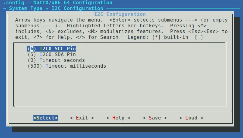
To enable the MPU6050 IMU, start by running make menuconfig in the NuttX project directory. Navigate to System Type → Peripheral Support and enable I2C0. On ESP32-C6 this should set GPIOs 6 and 5 as SCL and SDA pins, respectively. To verify, enter System Type → I2C Configuration to see the designated GPIOs.
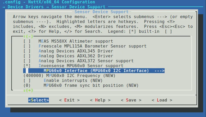
Then, go to Device Drivers → Sensor Device Support and enable the Invensense MPU60x0 Sensor support driver. Make sure to also select the MPU60x0 I2C Interface option, instead of SPI. Once these options are set, save your configuration and proceed to build the firmware.
Verify Device Registration#
To verify the IMU properly registered in the system, connect the IMU to the board and then build and flash the board:
make
make flash ESPTOOL_BINDIR=./ ESPTOOL_PORT=/dev/ttyUSB0
Open a serial terminal and check the available devices. You should now see /dev/imu0 among the other character drivers.
nsh> ls /dev
/dev:
 adc0
 console
 imu0
 motor0
 null
 pcnt0
 qe0
 random
 ttyS0
 zero
IMU Application#
Now that we have our devices configured, we need an application that is able to read the accelerometer data and send it to our computer, wirelessly.
To accomplish this, we’ll need to create another program similar to motor_sensing of the first article.
This program will read accelerometer data and open a socket that will be used to send the data.
The data transmitting part of this software will use a simple client/server socket, which is a widely available example for socket communication.
First, we need some definitions for the MPU6050 and for the socket:
#define REG_LOW_MASK    0xFF00
#define REG_HIGH_MASK   0x00FF
#define MPU6050_AFS_SEL 4096.0f   /* Accel scale factor */
#define SAMPLE_RATE_MS  20        /* 50 Hz sample rate */
#define TCP_PORT        5000      /* TCP port to send data */
#define MAX_MSG_SIZE    64        /* Maximum message size */
#define MAX_CLIENTS     1         /* Maximum number of clients */
Next, we need a data structure to hold the MPU6050 data. It must match the structure provided in the MPU6050 driver, which includes accelerometer, gyroscope, and temperature data.
struct mpu6050_imu_msg
{
  int16_t acc_x;
  int16_t acc_y;
  int16_t acc_z;
  int16_t temp;
  int16_t gyro_x;
  int16_t gyro_y;
  int16_t gyro_z;
};
This structure allows us to read the IMU through its file descriptor, which should be opened in the main function. On success, the raw IMU data must be converted to a usable value in units of g, which is achieved by concatenating the MSB and LSB registers to obtain a 16-bit integer and dividing the value by the AFS_SEL value, which is a scaling factor determined by the precision setting. More details about this can be found in the MPU6050 datasheet.
For the conversion function, we also need a simple structure to hold the processed accelerometer data:
struct sensor_accel
{
  float x;
  float y;
  float z;
};
The IMU reading function converts the raw sensor data to acceleration values in g-force units:
static void read_mpu6050(int fd, struct sensor_accel *acc_data)
{
  struct mpu6050_imu_msg raw_imu;
  int16_t raw_data[7];
  memset(&raw_imu, 0, sizeof(raw_imu));

  int ret = read(fd, &raw_data, sizeof(raw_data));
  if (ret != sizeof(raw_data))
    {
      printf("Failed to read IMU data\n");
      acc_data->x = 0;
      acc_data->y = 0;
      acc_data->z = 0;
      return;
    }

  /* Convert raw data */
  raw_imu.acc_x = ((raw_data[0] & REG_HIGH_MASK) << 8) +
                   ((raw_data[0] & REG_LOW_MASK) >> 8);
  raw_imu.acc_y = ((raw_data[1] & REG_HIGH_MASK) << 8) +
                   ((raw_data[1] & REG_LOW_MASK) >> 8);
  raw_imu.acc_z = ((raw_data[2] & REG_HIGH_MASK) << 8) +
                   ((raw_data[2] & REG_LOW_MASK) >> 8);

  /* Convert to g force */
  acc_data->x = raw_imu.acc_x / MPU6050_AFS_SEL;
  acc_data->y = raw_imu.acc_y / MPU6050_AFS_SEL;
  acc_data->z = raw_imu.acc_z / MPU6050_AFS_SEL;
}
Now, we create our main function which opens the IMU file descriptor, reads it and also establishes network communication.
The main function performs the following steps:
- Opens and checks if the IMU device is available
- Creates a TCP socket and waits for a connection from client
- Once a connection is established, accepts the client and starts reading IMU data
- Sends the data over the network connection
- Monitors for client disconnections and waits for reconnection when needed
This process repeats every 20 ms, as defined by the SAMPLE_RATE_MS value.
The following code is also available in the example repository.
int main(int argc, FAR char *argv[])
{
  int fd;
  struct sensor_accel acc_data;
  char msg_buffer[MAX_MSG_SIZE];

  /* Socket variables */
  int server_fd, client_fd;
  struct sockaddr_in server_addr, client_addr;
  socklen_t client_len = sizeof(client_addr);
  int opt = 1;

  printf("MPU60x0 Accelerometer Test\n");
  printf("Sample Rate: %d ms (%d Hz)\n", SAMPLE_RATE_MS, 1000/SAMPLE_RATE_MS);
  printf("TCP server starting on port %d\n", TCP_PORT);

  /* Open IMU device */
  fd = open("/dev/imu0", O_RDONLY);
  if (fd < 0)
    {
      printf("Failed to open imu0\n");
      return EXIT_FAILURE;
    }

  /* Create TCP socket */
  server_fd = socket(AF_INET, SOCK_STREAM, 0);
  if (server_fd < 0)
    {
      printf("Failed to create socket\n");
      close(fd);
      return EXIT_FAILURE;
    }

  /* Set socket options */
  if (setsockopt(server_fd, SOL_SOCKET, SO_REUSEADDR,
                 &opt, sizeof(opt)) < 0)
    {
      printf("Failed to set socket options\n");
      close(fd);
      close(server_fd);
      return EXIT_FAILURE;
    }

  /* Configure server address */
  memset(&server_addr, 0, sizeof(server_addr));
  server_addr.sin_family = AF_INET;
  server_addr.sin_addr.s_addr = INADDR_ANY;
  server_addr.sin_port = htons(TCP_PORT);

  /* Bind socket */
  if (bind(server_fd, (struct sockaddr *)&server_addr,
           sizeof(server_addr)) < 0)
    {
      printf("Failed to bind socket\n");
      close(fd);
      close(server_fd);
      return EXIT_FAILURE;
    }

  /* Listen for connections */
  if (listen(server_fd, MAX_CLIENTS) < 0)
    {
      printf("Failed to listen\n");
      close(fd);
      close(server_fd);
      return EXIT_FAILURE;
    }

  printf("Waiting for client connection...\n");

  /* Accept client connection */
  client_fd = accept(server_fd, (struct sockaddr *)&client_addr,
                    &client_len);
  if (client_fd < 0)
    {
      printf("Failed to accept client\n");
      close(fd);
      close(server_fd);
      return EXIT_FAILURE;
    }

  printf("Client connected\n");

  while (1)
    {
      read_mpu6050(fd, &acc_data);

      /* Format data as string with newline */
      snprintf(msg_buffer, MAX_MSG_SIZE, "%.3f,%.3f,%.3f\n",
               acc_data.x, acc_data.y, acc_data.z);

      /* Send data over TCP */
      ssize_t bytes_sent = send(client_fd, msg_buffer,
                               strlen(msg_buffer), 0);

      /* Check if client disconnected */
      if (bytes_sent <= 0)
        {
          printf("Client disconnected, waiting for new connection...\n");
          close(client_fd);

          /* Wait for new client */
          client_fd = accept(server_fd, (struct sockaddr *)&client_addr,
                           &client_len);
          if (client_fd < 0)
            {
              printf("Failed to accept new client\n");
              break;
            }
          printf("New client connected\n");
          continue;
        }

      printf("Accel (g): X=%.3f Y=%.3f Z=%.3f\n",
             acc_data.x, acc_data.y, acc_data.z);

      usleep(SAMPLE_RATE_MS * 1000);
    }

  /* Cleanup */
  close(fd);
  close(client_fd);
  close(server_fd);
  return EXIT_SUCCESS;
}
Client-Side Data Acquisition#
Now that we have everything set up on our ESP32-C6, we just need a simple program to wirelessly connect to our board and obtain this data.
This client program can be built in many ways using Python’s sockets module, C sockets or even a bash script.
For the sake of simplicity, we’ll use a bash script. The following snippet connects to our server using netcat and prints the received data.
#!/bin/bash

# Default connection parameters
HOST="10.42.0.199"
PORT=5000

# Check if custom host/port provided
if [ $# -eq 2 ]; then
    HOST=$1
    PORT=$2
fi

echo "Connecting to IMU server at $HOST:$PORT..."

# Connect to server and process data
nc $HOST $PORT | while IFS="," read -r x y z; do
    printf "X: %6s  Y: %6s  Z: %6s\r" "$x" "$y" "$z"
done

echo -e "\nConnection closed."
Testing Application#
With the IMU and socket program ready, we enable it through menuconfig on Application Configuration → Motor Sensing Apps → Motor IMU Data Example, build and flash the board.
The imu program should now be available on the NuttShell. Make sure you are connected to a Wi-Fi network.
Execute the IMU program on NuttX:
nsh> imu
MPU60x0 Accelerometer Test
Sample Rate: 20 ms (50 Hz)
TCP server starting on port 5000
Waiting for client connection...
Now run the client-side bash script. You should see data being received:
$ ./imu_client.sh
Connecting to IMU server at 10.42.0.199:5000...
X:  1.168  Y: -0.077  Z:  0.145
Exiting the bash script and restarting should keep the data flowing with no issues.
Practical Use#
To fulfill the initial proposal of measuring motor vibrations, we can now change the motor speed by moving the potentiometer and log this data for analysis.
The following figure shows the results of a simple test where the motor was stopped, then speed gradually increased and decreased until a full stop.
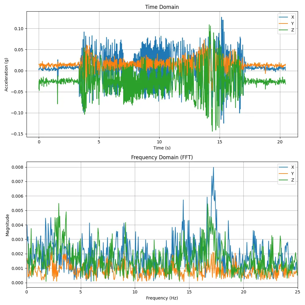
The data and script used to generate the plots are available on the example repository.
Conclusion#
In this second part of the NuttX motor control series, we successfully transformed a basic motor control system into a complete networked sensing platform. Building on the foundation established in the first article, we’ve now added sensing and connectivity capabilities.
In summary, the achievements in this article include:
- Wi-Fi connectivity integration: Configured and connected the ESP32-C6 to wireless networks using NuttX’s networking stack
- IMU sensor integration: Implemented MPU6050 accelerometer support via I2C for vibration measurement
- Wireless data streaming: Created a TCP socket-based system for streaming sensor data from the embedded device to a host computer
- Cross-platform communication: Developed both embedded firmware and host-side client scripts for data exchange
The combination of both articles demonstrates how NuttX can be used to build advanced embedded systems that bridge the gap between traditional motor control and modern IoT applications. We started with basic motor control using familiar peripherals and evolved into a comprehensive system capable of wireless sensor data streaming, creating a complete embedded IoT platform.