
Introduction#
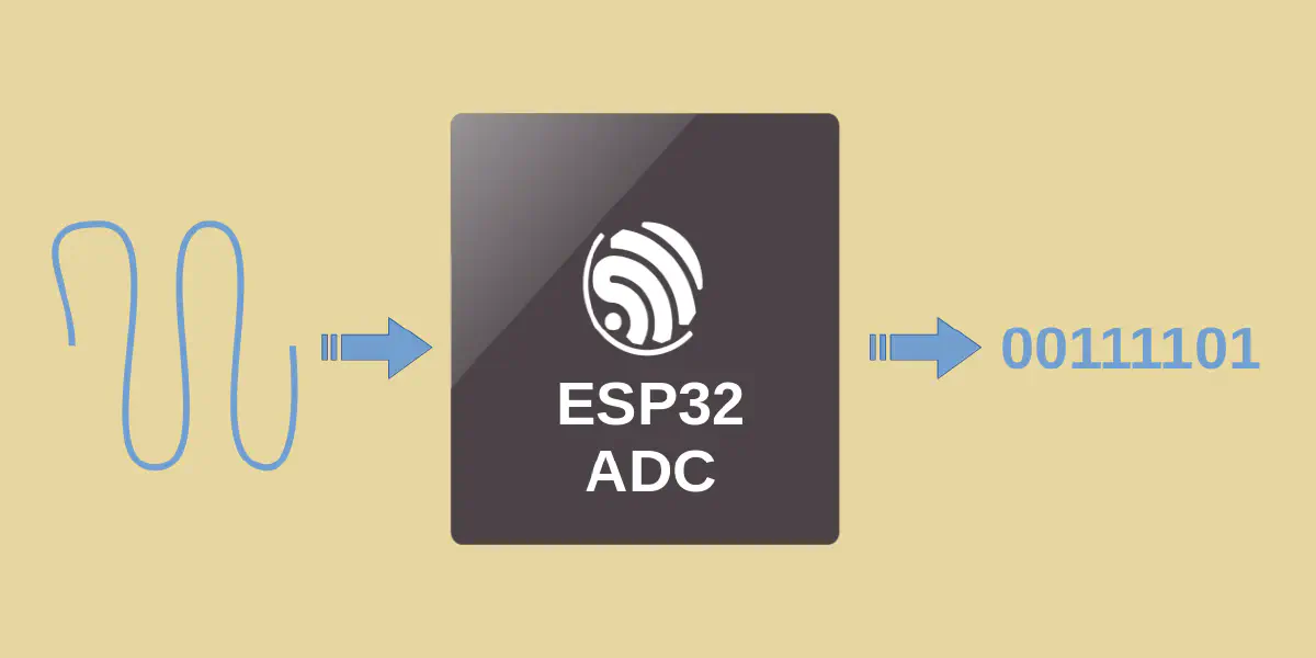
An Analog-to-Digital Converter (ADC) is essential for bridging the gap between the physical analog world and digital systems. It is widely used to bring analog signals — for example, temperature, sound, and voltage — into the digital domain for further processing. The accuracy of an ADC depends on its specifications, including resolution, range, and sampling rate. Additionally, various factors can further affect accuracy, such as offset and gain errors, non-linearity (DNL and INL), and temperature drift.
In this article, we will dive into technical details, discuss the accuracy of different Espressif SoCs, and explore techniques to calibrate and improve their accuracy. The following Espressif SoCs will be covered:
- ESP32
- ESP32-S2
- ESP32-S3
- ESP32-C3
- ESP32-C2
- ESP32-C6
- ESP32-H2
- ESP32-P4
- ESP32-C5
ADC Technical Specifications#
Espressif SoCs integrate either one or two ADC peripherals capable of measuring analog signals on dedicated IO pins. The table below compares some of their specifications. The specifications can be found in respective datasheets.
| SAR ADC | Resolution | Channels | Range (mV) | DNL | INL | Sampling rate (Ksps) | Variation among samples | |
|---|---|---|---|---|---|---|---|---|
| x2 | 12-bit | 8+10 | 150 ~ 2450 | ±7 | ±12 | RTC: 200 DIG: 2000 | ±6 % | |
| x2 | 13-bit | 10+10 | 0 ~ 2500 | ±7 | ±12 | - | - | |
| x2 | 12-bit | 10+10 | 0 ~ 2900 | ±4 | ±8 | 100 | ±100 mV | |
| x2 | 12-bit | 6 | 0 ~ 2500 | ±7 | ±12 | 100 | - | |
| x1 | 12-bit | 5 | 0 ~ 2800 | +3, -1 | +8, -4 | 100 | - | |
| x1 | 12-bit | 7 | 0 ~ 3300 | +12, -8 | ±10 | 100 | - | |
| x1 | 12-bit | 5 | 0 ~ 3300 | +12, -8 | ±10 | 100 | - | |
| x2 | 12-bit | 14 | 0 ~ 3300 | +3, -1 | +3, -5 | 100 | - | |
| x1 | 12-bit | 6 | 0 ~ 3300 | ±5 | ±5 | 2000 | - |
Table 1. ADC Specifications Comparision
ADC Calibration#
In ESP-IDF, an ADC calibration driver is provided to calibrate the raw ADC readings during conversion. The calibration driver helps improve the accuracy by reducing most of the errors.
The ADC calibration driver provides ADC calibration schemes. Espressif SoCs support either Line Fitting scheme or Curve Fitting scheme. Line Fitting scheme applies linear transformation in calibration, while Curve Fitting scheme applies non-linear transformation. Calibration schemes contain algorithms and built-in coefficients for converting input raw readings to final output voltage reading. These coefficients are carefully tuned in production line to work on all chips in mass production. The calibration driver also provides APIs to implement custom ADC calibration schemes. However, custom calibration schemes may not work well on all chips, and hence not recommended for mass production.
The list below shows the calibration schemes for each series of Espressif SoC.
- ESP32: Line Fitting
- ESP32-S2: Line Fitting
- ESP32-S3: Curve Fitting
- ESP32-C3: Curve Fitting
- ESP32-C2: Line Fitting
- ESP32-C6: Curve Fitting
- ESP32-H2: Curve Fitting
- ESP32-P4: Curve Fitting
- ESP32-C5: Curve Fitting
ADC Accuracy Performance#
Here we measure and present a visual demonstration of the overall ADC accuracy performance of Espressif SoCs. In the measurement, we adjust the input voltage in a 10 mV step over time and take the raw value read from the ADC. We then calculate the calibrated voltage from the raw value readings. The measured ADC performance of each SoC is presented in two ways:
- Time Graph: This shows the Input/Output voltage reading over time. It allows us to verify whether the linearity of ADC is as expected. There are 3 lines in the graph:
- Raw value: Represent raw reading based on the bit width. With a 12-bit resolution, the range of the raw value is from 0 to 4095.
- Smooth value: Represent calibrated output voltage reading.
- Base line: Represent input voltage to ADC.
- Error Graph: This shows the error distribution over voltage. It allows us to view the error range across the supported voltage levels.
Note that measurement result on individual chip may slightly differ from the overall SoC performance. For overall result specification, please follow the SoC datasheet.
ESP32#
This graph shows the input/output voltage reading over time for ESP32.
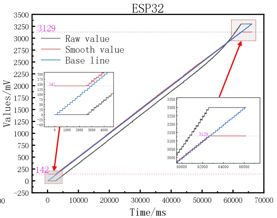
Fig 1. ESP32 Time Graph
In Fig 1., we see that the raw reading of ESP32 exhibits offset error. It also shows nonlinearity error at the higher voltage range. However, after calibration, both offset error and nonlinearity are greatly improved. The range is still limited at the start and end of the full-range, mostly due to the offset error.
The deviation after calibration cannot be clearly visualized in the voltage over time graph. This can be viewed from the error over voltage graph:
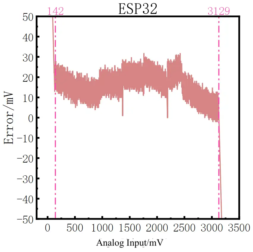
Fig 2. ESP32 Error Graph
From the graph, we can see that, aside from the loss of readings at the beginning and end of the range, the calibrated error is generally less than 30 mV in this measurement. Interestingly, the calibration performs better in the range where the raw readings exhibit non-linearity issues; in this region, the error gradually reduces toward zero.
ESP32-S2#
The time graph shows that the ESP32-S2 suffers from gain error but has better linearity than the ESP32. Calibration can correct the gain error, however, the usable range at the end is lost due to this error.
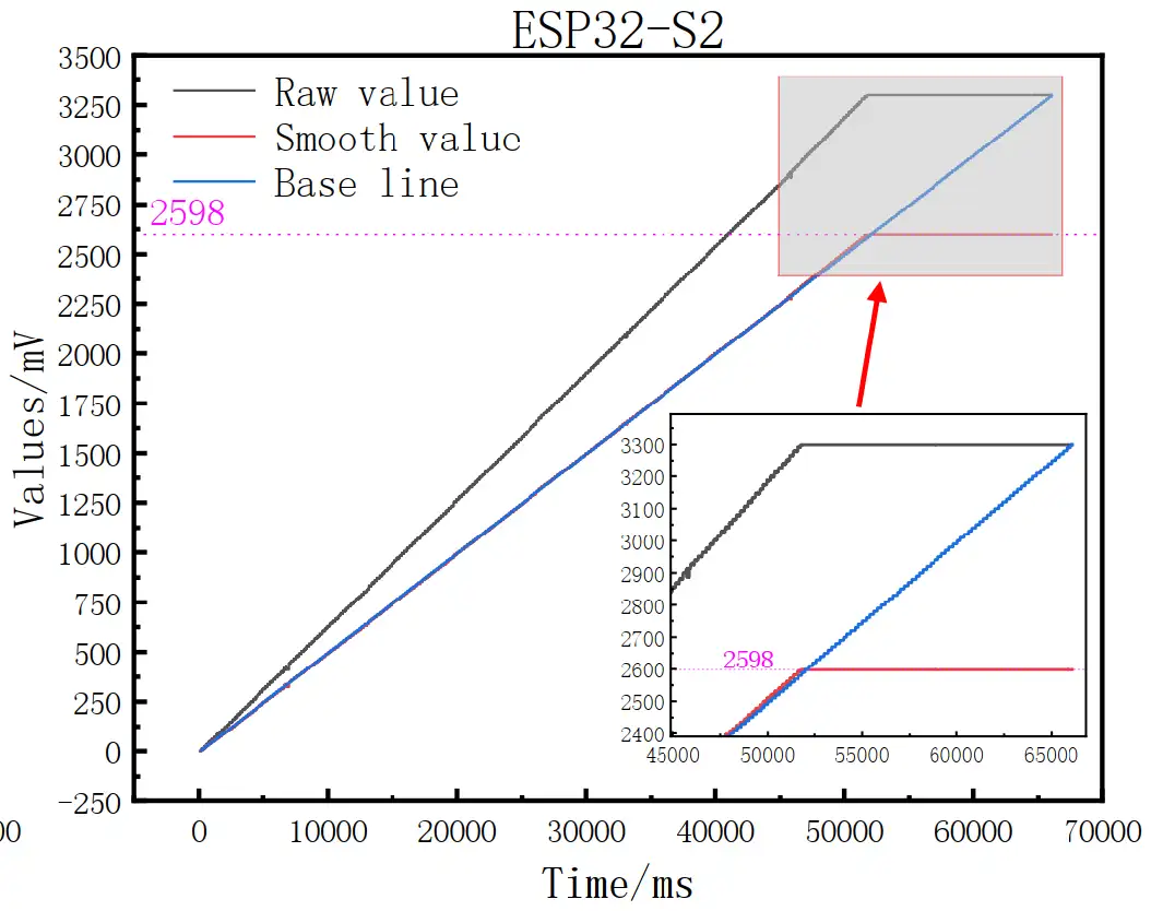
Fig 3. ESP32-S2 Time Graph
From the error graph the calibrated ESP32-S2 performs much better than the ESP32 in the lower range. However, the error starts to increase gradually when the input voltage exceeds 2200 mV.
ESP32-S2 is best for applications requiring high accuracy in low voltage range.
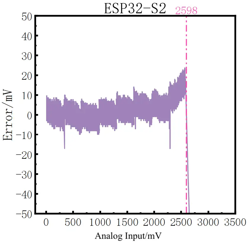
Fig 4. ESP32-S2 Error Graph
ESP32-S3#
From the time graph, the ESP32-S3 shows good linearity with minimal offset and gain errors in the low-voltage range. At around 2750 mV, it starts to exhibit non-linearity. The calibration corrects the curve but results in a loss of measurements at the higher voltage range.
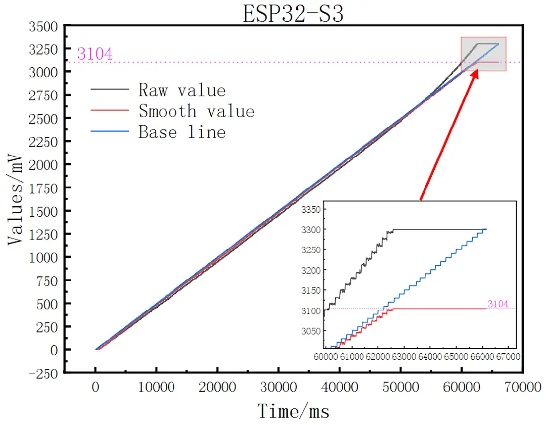
Fig 5. ESP32-S3 Time Graph
The error flucturates between -30 to 0 mV until the output cuts off.
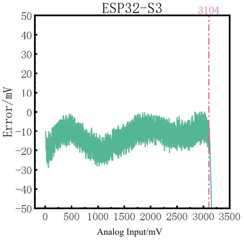
Fig 6. ESP32-S3 Error Graph
ESP32-C3#
The raw readings show that the ESP32-C3 exhibits gain error and slight non-linearity at higher voltage ranges. The calibration scheme corrects the gain error, but a relatively high error still persists at the upper voltage range. In this measurement, the voltage range reaches 2890 mV, and the error increases to about 50 mV at high voltages. Note that the voltage range in specification is up to 2500 mV.
It is suggested that designers avoid using the ADC on the ESP32-C3 at higher voltage ranges.
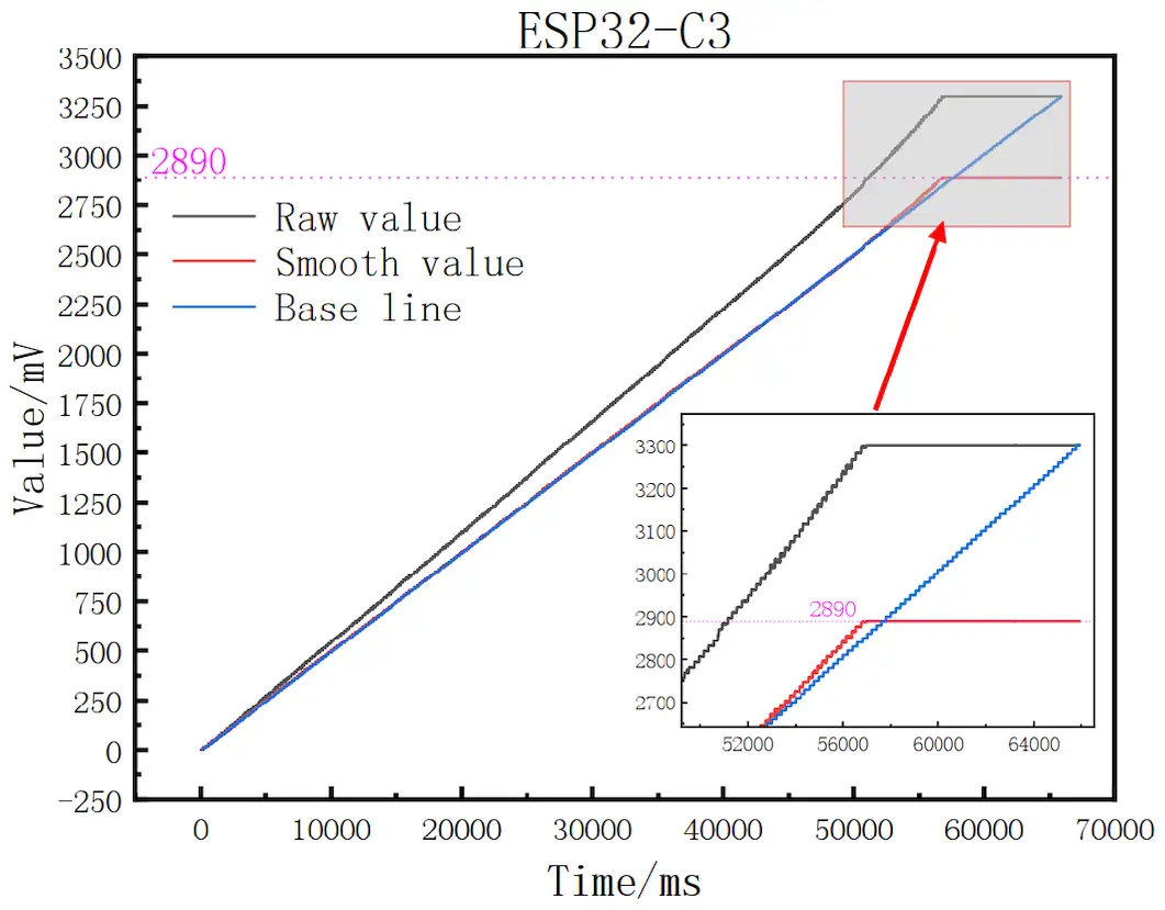
Fig 7. ESP32-C3 Time Graph
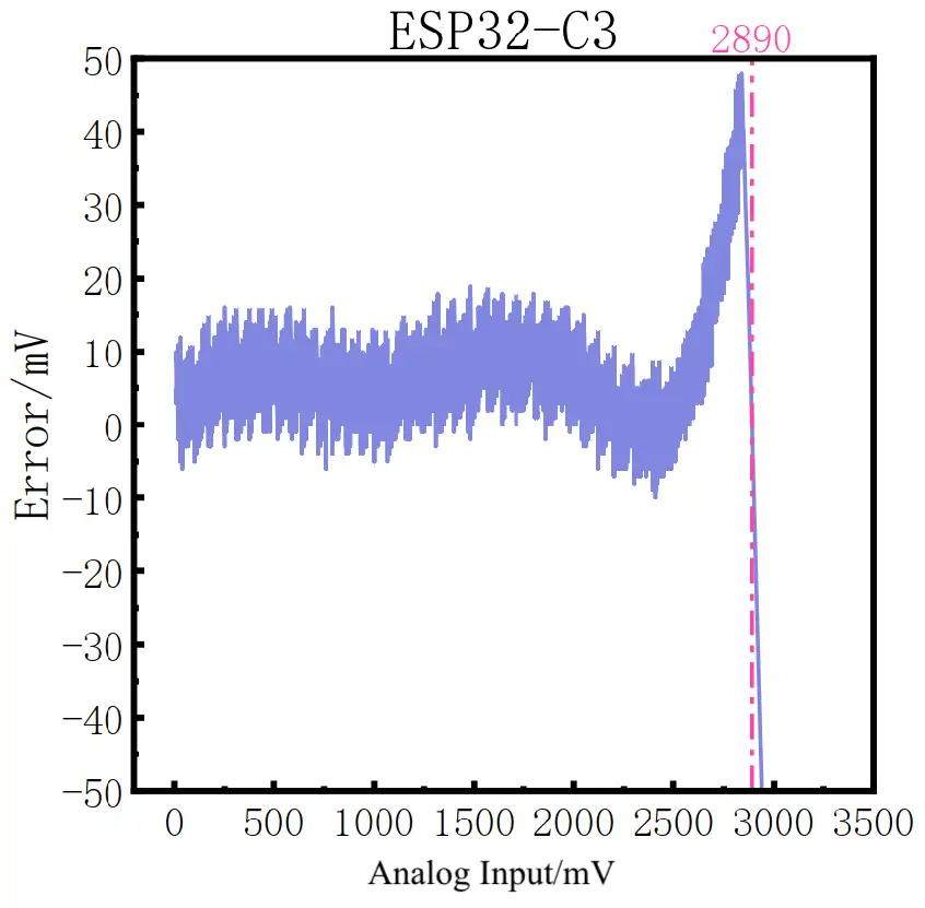
Fig 8. ESP32-C3 Error Graph
ESP32-C2#
From the graph, the ESP32-C2 raw readings show a negative gain error, which is corrected well after calibration. The error range after calibration is only about ±10 mV. The ESP32-C2 is recommended for applications that require high ADC accuracy. However, according to the specification, the voltage range is limited to 2800 mV. It is suggested to avoid operating at higher voltage ranges in mass production.
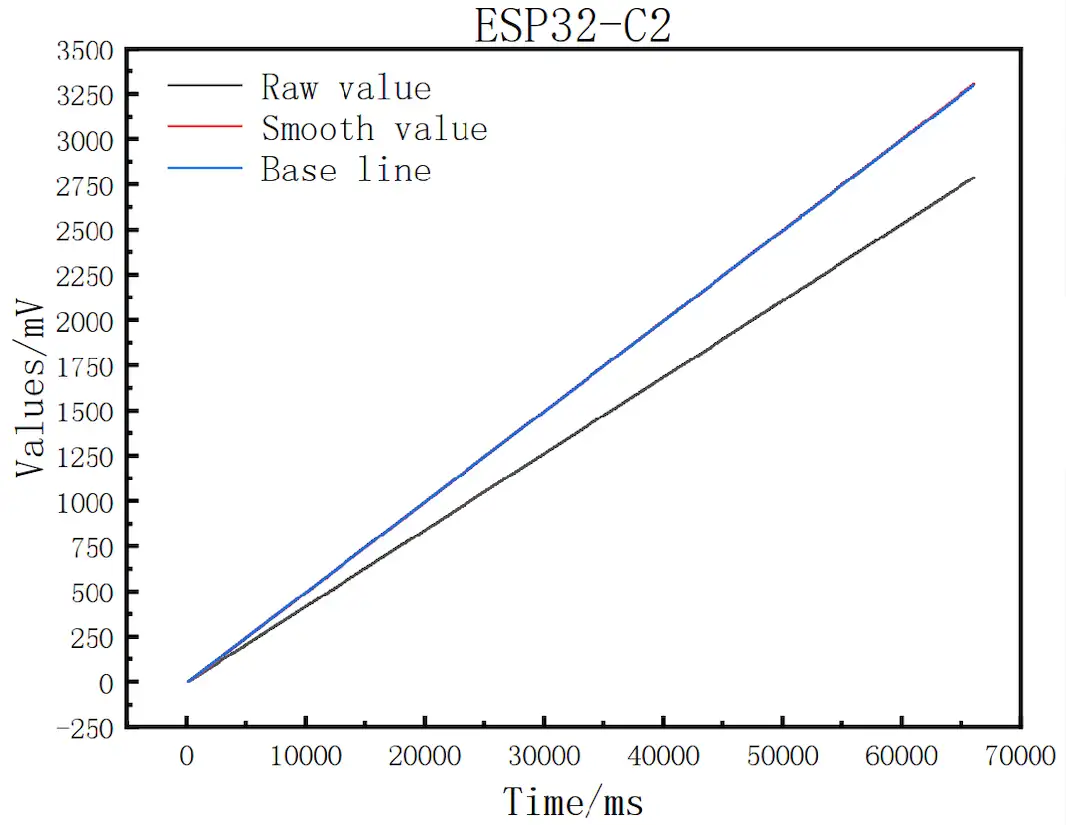
Fig 9. ESP32-C2 Time Graph
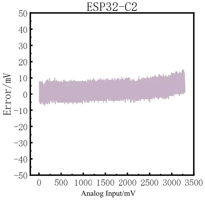
Fig 10. ESP32-C2 Error Graph
ESP32-C6#
The ESP32-C6 ADC is able to perform full-range conversion. The raw readings show a negative gain error, which is effectively corrected through calibration, limiting the error to around ±10 mV. As the voltage increases, the error range shifts slightly upward to approximately +20 to 0 mV. Overall, the error range is ±40 mV according to the specification. The ESP32-C6 ADC can be used for full-range applications that require average accuracy.
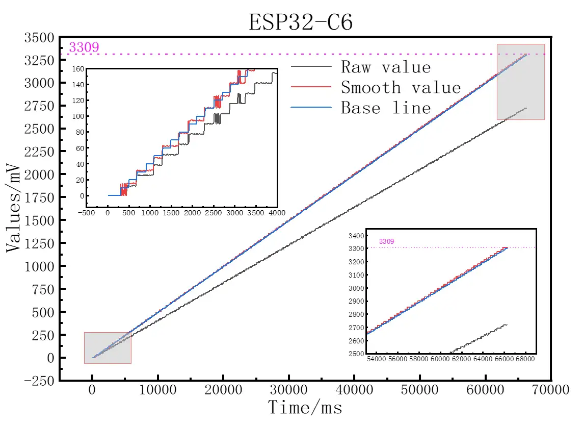
Fig 11. ESP32-C6 Time Graph
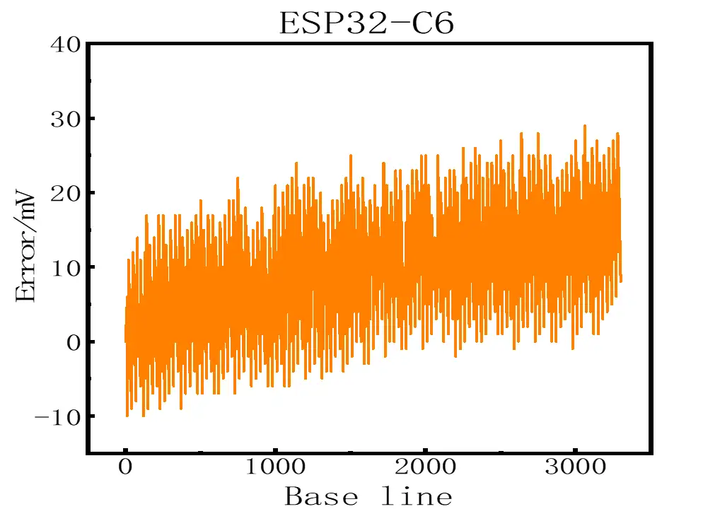
Fig 12. ESP32-C6 Error Graph
ESP32-H2#
Similar to the ESP32-C6, the ESP32-H2 ADC is able to perform full-range conversion, with raw readings showing a negative gain error. Calibration effectively limits the error in the range of ±23 mV, according to the specification. The ESP32-H2 ADC is suitable for full-range applications requiring higher accuracy than the ESP32-C6 can offer.
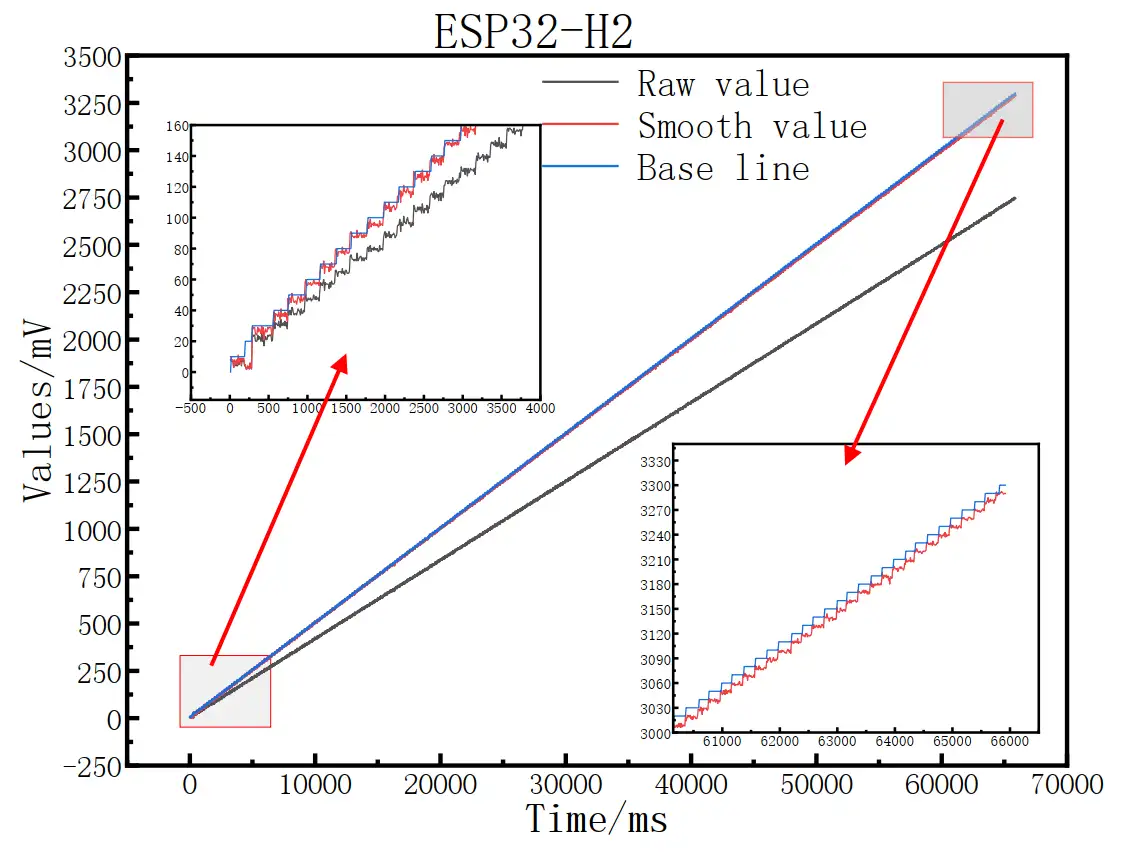
Fig 13. ESP32-H2 Time Graph
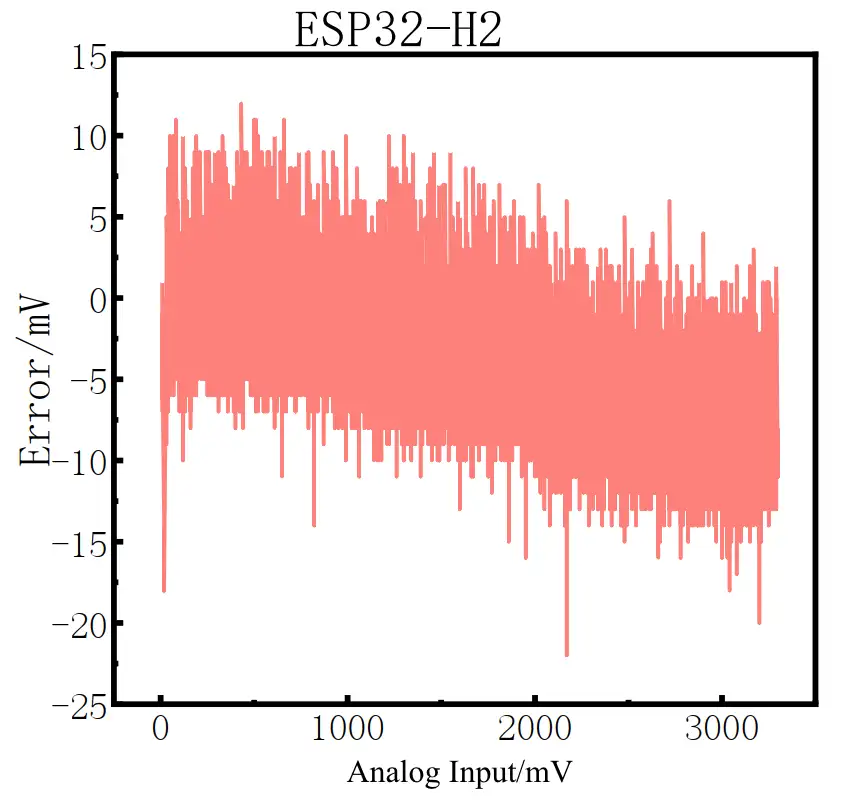
Fig 14. ESP32-H2 Error Graph
ESP32-P4#
The ESP32-P4 ADC is also able to perform full-range conversion, though it exhibits a negative gain error. After calibration, the error remains consistent, within ±15 mV, across the full range. Its accuracy is very close to that of the ESP32-C2, with the added advantage of full-range measurement capability. It is recommended for full-range, high-accuracy applications.
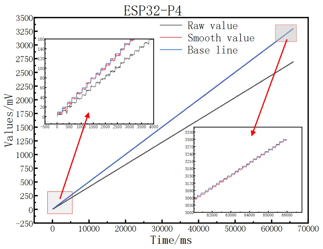
Fig 15. ESP32-P4 Time Graph
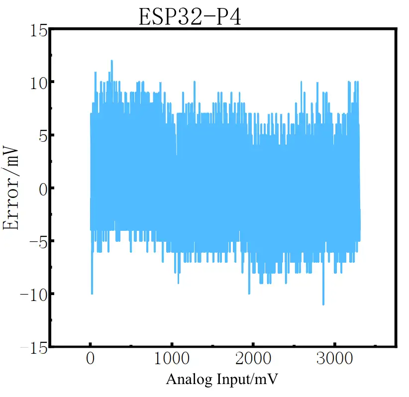
Fig 16. ESP32-P4 Error Graph
ESP32-C5#
The ESP32-C5 ADC has similar performance to the ESP32-P4, with slightly higher accuracy in the lower voltage range. It is also recommended for high-accuracy applications.
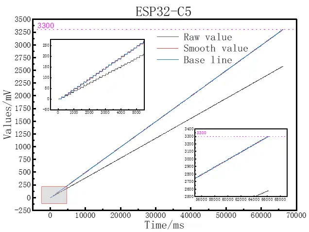
Fig 17. ESP32-C5 Time Graph
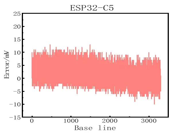
Fig 18. ESP32-C5 Error Graph
ADC Range Extension#
As you can see from the graphs presented above, some SoCs do not support full-scale measurement (0–3300 mV). However, full-scale measurement may be required for certain applications. To address this, we provide an ADC range extension solution for the ESP32-S2 and ESP32-S3. The solution is available as a patch for ESP-IDF v4.x and v5.x, respectively.
Noise Impact#
Noise can affect ADC measurements, causing variations between readings of the same input voltage. The documentation recommends connecting a bypass capacitor (e.g., a 100 nF ceramic capacitor) to the ADC input pad to minimize noise. In addition, the technique of multisampling can further reduce the impact of noise.
Temperature Drift#
Temperature drift can affect ADC accuracy when the operating temperature deviates significantly from normal conditions. A temperature compensation algorithm is currently under development for Espressif SoCs that support a curve-fitting scheme. The impact of temperature drift is carefully studied for each SoC and expressed in formulas and coefficients. These formulas and coefficients are then applied during calibration calculations based on readings from the on-board temperature sensor. This feature is expected to be available in ESP-IDF later this year.
ADC Performance Comparison Among SoCs#
The graph below provides an overview to help designers choose the right Espressif SoC for applications with different requirements. Note that the graph is based on worst-case figures from the specification. Using lower attenuation settings and applying optimization techniques, it is possible to achieve better performance.
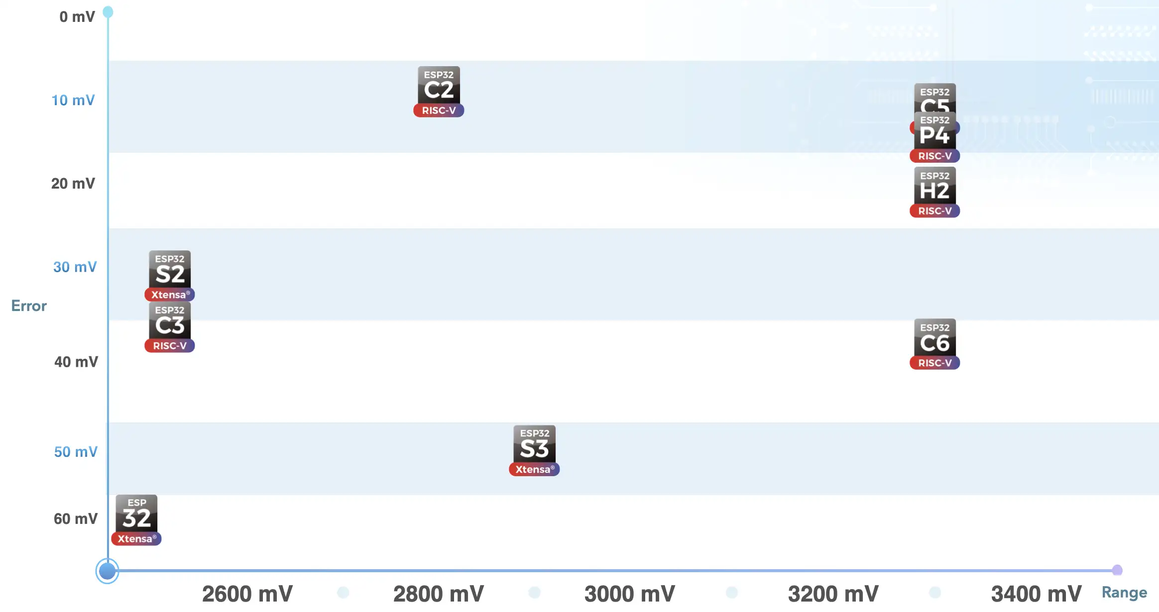
Fig 17. ADC Selection Matrix
The ESP32-C2, ESP32-C5, ESP32-P4, ESP32-C6, and ESP32-H2 series can perform full-range measurement. Among them, the ESP32-H2, ESP32-P4, and ESP32-C5 have similar performance and work well in applications requiring high-accuracy ADC performance.
Other SoCs have a shorter measurement range. However, there is a solution to extend the ADC range for the ESP32-S2 and ESP32-S3.
The ESP32 and ESP32-S3 exhibit relatively poorer error performance. Their error characteristics and voltage range should be carefully considered before using them in ADC applications.
In addition, sampling rate is also an important factor to consider. Both the ESP32 and ESP32-C5 can achieve higher sampling rates than the others, reaching up to 2000 ksps.
Conclusion#
In this article, we explored the technical specifications of the ADCs in Espressif SoCs and discussed their accuracy after calibration. We also introduced ongoing efforts to improve range, noise, and temperature drift performance.
With this information, designers can make more informed decisions when selecting the appropriate SoC for their specific ADC application needs.