
In the world of IoT devices, reducing power consumption is key to extending battery life. One of the most effective strategies to achieve this is by putting the device to sleep. The longer it stays asleep, the more power it saves. Espressif SoCs support multiple sleep modes to manage this, with Deep-sleep being the most power-efficient. But traditional Deep-sleep has a downside: every time the device wakes up, it has to go through a full boot process, even if the device only needs to perform a quick task before going back to sleep. Thus, it ends up wasting precious energy.
That’s where the wake stub comes in. It changes the game by letting the chip skip most of the boot sequence and jump straight into a critical task. This means the chip wakes up faster, uses less power, and only initializes the peripherals it actually needs. Whether it’s a soil sensor in smart farming or a step counter in a wearable device, this feature can greatly extend battery life.
Although the ULP coprocessor can also help save power, its use cases differ from wake stubs, mainly due to the limited resources available when the HP core is in deep sleep. In Deep-sleep mode, the HP core, most of the RAM (excluding RTC/LP memory), and all HP peripherals on Espressif chips are powered off. While the ULP remains powered, its functionality and accessible memory are limited. For details on which modules remain powered during deep sleep, please refer to the Functional Block Diagram in Datasheet. In contrast, the wake stub can access all peripherals and RAM, and therefore supports more complex functionality.
In this article, we’ll take a closer look at how the Deep-sleep wake stub works and show how to build a Deep-sleep wake stub application on Espressif chips.
Deep-Sleep Wake Stub Application#
After SoC reset, the CPU will start running immediately to perform initialization (known as the first-stage ROM bootloader). Depending on the reset reason, the system follows different execution paths, as illustrated in the figure below.
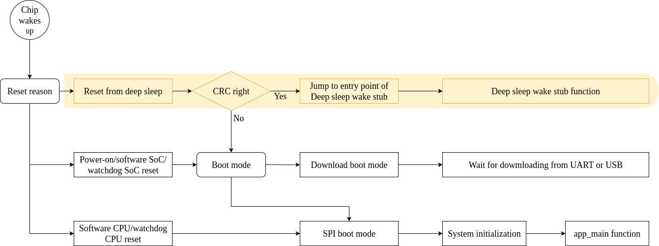
Reset from deep sleep: After partial initialization, the CPU performs a CRC check on the RTC/LP memory to ensure the data is valid. If the check passes, the CPU jumps to the entry point of the Deep-sleep wake stub application stored in RTC/LP Memory and begins execution. Otherwise, it proceeds with SPI boot mode.
For power-on reset, software SoC reset, and watchdog SoC reset: The chip enters Download boot mode or SPI boot mode.
For software CPU reset and watchdog CPU reset: The chip directly enters SPI boot mode and runs port and system initialization. This includes setting up internal memory sections (data and BSS) and watchdog timers . It then jumps to the user application entry point—
app_main().
From the boot process after SoC reset, we can see that Espressif chips can skip full system initialization and directly execute the Deep-sleep wake stub application. Thus, the Deep-sleep wake stub application is particularly well-suited for the following two scenarios:
Periodic lightweight tasks: the wake stub can handle them without booting the entire chip, allowing it to either return to sleep quickly or continue the boot process, thereby saving power.
To implement such tasks using GPIO, UART, I2C, and SPI in the wake stub, see Implementation of Wake Stub Functionality.
Tasks with real-time requirements: the wake stub can execute them before continuing the boot process, greatly speeding up wake-up response and improving overall application performance.
An example of such use case is covered in the article Boot Secure, Restore Smart: Accelerating Device Startup on ESP32, where hardware peripherals in the ESP-IDF bootloader are manipulated to shorten device boot-up delays. This approach reduced the boot-up time of a smart lighting system from 405 ms to 85 ms. Even more impressively, using a wake stub can bring that down to just 6 ms—significantly accelerating system startup.
The current support status for Deep-sleep wake stub applications on Espressif chips is summarized in the table below.
| Chips | Support |
|---|---|
| ESP32 | Yes |
| ESP32-S2 | Yes |
| ESP32-S3 | Yes |
| ESP32-C2 | No* |
| ESP32-C3 | Yes |
| ESP32-C5 | Yes |
| ESP32-C6 | Yes |
| ESP32-H2 | Yes |
| ESP32-P4 | No** |
*The chip ESP32-C2 lacks RTC/LP Memory; therefore, all memory is powered down during deep sleep, preventing storage of wake stub code.
**Although the chip ESP32-P4 does not support a wake stub, the LP core has its own ROM to boot itself and handle tasks while the HP core stays in deep sleep.
Implement Wake Stub#
This article takes the ESP32-C6 as an example to further explain the principles of Deep-sleep wake stub. When executing the wake stub application, the chip has not yet completed the configuration of internal memory sections or watchdog timers. Therefore, when developing a wake stub application, it is important to pay special attention to memory usage constraints and watchdog configuration.
Memory Allocation#
When executing the wake stub application, the chip has not yet completed system initialization—only RTC/LP Memory and ROM are available, while all other SRAM regions remain uninitialized and may contain random data. Therefore, all functions and data used by the wake stub must be explicitly placed in RTC/LP Memory. It is important to note, however, that although SRAM is uninitialized, it is already powered on; thus, dynamic data such as local variables can be used directly without special handling.
ESP-IDF provides dedicated methods for placing functions and data in RTC/LP Memory.
Placing Functions in RTC/LP Memory
Use the
RTC_IRAM_ATTRattribute to place the wake stub function in RTC/LP Memory. This method is suitable for short and simple code segments or for source files including both “normal” and “RTC” code. The function should be defined as:void RTC_IRAM_ATTR wake_stub(void) { }.Alternatively, place the wake stub function into any source file with such names
*rtc_wake_stub*.Their contents can be automatically put into RTC/LP memory by the linker.
Placing Data in RTC/LP Memory
Use the
RTC_DATA_ATTRandRTC_RODATA_ATTRattributes to place writable and read-only data, respectively. Note that string constants must be declared as arrays and marked withRTC_RODATA_ATTR.Alternatively, place the data in any source file with such names
*rtc_wake_stub*. The linker will ensure such data is placed into RTC/LP Memory.
The attributes
RTC_FAST_ATTRandRTC_SLOW_ATTRcan be used to specify data that will be force placed into RTC/LP memory and RTC slow memory respectively. However, ESP32-C6 includes RTC/LP memory only, so both these two attributes will map to this region.
Memory Capacity#
The wake stub application is constrained by the limited size of RTC/LP Memory (16 KB), which makes it infeasible to directly include full peripheral driver code (e.g., for GPIO or UART). To use such peripherals within a wake stub, you can adopt one of the following approaches:
- Use LL (Low-Level) API interfaces to control peripherals. These interfaces are typically defined in header files, with minimal code size, making them well-suited for RTC/LP Memory. The next section of this article provides programming examples for using GPIO, UART, I2C, and SPI in wake stub applications based on LL APIs.
The LL APIs are not guaranteed to remain stable and may change without notice in new releases. Developers are advised to use them with caution and at their own risk.
- IDF peripheral driver code can be stored in flash and either executed directly via MMU mapping or loaded into SRAM via the SPI interface. When using such drivers in the wake stub, you must manually initialize any required system components (e.g., clocks, interrupts), as these are not initialized.
During wake-up, the RWDT and MWDT0 watchdog timers are enabled to prevent system hangs in the bootloader stage. In SPI boot mode, these watchdog timers are disabled during system initialization. However, in a wake stub application, initialization has not yet occurred, so both timers remain active. If the wake stub performs complex or time-consuming tasks, it must feed the watchdogs to avoid an unexpected reset.
How to Create a Deep-Sleep Wake Stub Application#
This section provides a detailed guide on creating a wake stub application and demonstrates how to implement GPIO, UART, I2C, and SPI functionalities using LL-layer APIs within this application. All example code is based on the ESP-IDF v5.5 and uses the ESP32-C6 as the development platform.
Build System#
To implement a wake stub application, we first create a directory, which contains a CMakeLists.txt file defining the build rules and a main/ subdirectory for the source code. The content of the project’s CMakeLists.txt file is as follows:
# Set the minimum required CMake version
cmake_minimum_required(VERSION 3.16)

# Include other cmake files into the current file
include($ENV{IDF_PATH}/tools/cmake/project.cmake)
# "Trim" the build.
idf_build_set_property(MINIMAL_BUILD ON)
# Set the project name
project(deep_sleep_wake_stub)
The main/ subdirectory should also include a CMakeLists.txt file to register the wake stub application and integrate it into the build system.
idf_component_register(SRCS "wake_stub_example_main.c"
                            "rtc_wake_stub_example.c"
                    INCLUDE_DIRS ".")
Register the Wake Stub Application#
In the wake_stub_example_main.c file, we can write the code to be executed when the chip completes initialization. The function void app_main(void) serves as the entry point where the CPU jumps after power-on reset and SPI boot mode.
To enable the Deep-sleep wake stub application, we need to register the wake stub function within the app_main() function. The steps are as follows:
Configure Deep-sleep wakeup sources. The Deep-sleep wakeup sources for the ESP32-C6 chip include LP GPIO, Wi-Fi beacon, RTC Timer, and LP CPU. These wake-up sources can be configured by including the
esp_sleep.hheader file and using the relevant APIs.Register the wake stub function. To execute a wake stub application after the chip wakes from deep sleep, we need to register a user-defined wake stub function by using the
esp_set_deep_sleep_wake_stubfunction defined inesp_sleep.h. Its function prototype is as follows:void esp_set_deep_sleep_wake_stub(esp_deep_sleep_wake_stub_fn_t new_stub);Here,
new_stubis a function pointer that points to a function with no parameters and no return value.Explicitly enter Deep-sleep mode by calling the
esp_deep_sleep_start()function function defined inesp_sleep.h.Jump to execute the registered wake stub application when the wake-up condition is met.
Here is an example of wake_stub_example_main().
Implementation of Wake Stub Functionality#
Assume a wake stub function wake_stub_example() has been registed in the user application. Now, we introduce its typical structure.
#include <inttypes.h>
#include "esp_sleep.h"
#include "esp_cpu.h"
#include "esp_rom_sys.h"
#include "esp_wake_stub.h"
#include "sdkconfig.h"

// counter value, stored in RTC memory
RTC_DATA_ATTR uint32_t s_count = 0;
RTC_DATA_ATTR const uint32_t s_max_count = 20;

// wakeup_cause stored in RTC memory
RTC_DATA_ATTR uint32_t wakeup_cause;

// wakeup_time from CPU start to wake stub
RTC_DATA_ATTR uint32_t wakeup_time;

// wake up stub function stored in RTC memory
void wake_stub_example(void)
{
    // Get wakeup time.
    wakeup_time = esp_cpu_get_cycle_count() / esp_rom_get_cpu_ticks_per_us();
    // Get wakeup cause.
    wakeup_cause = esp_wake_stub_get_wakeup_cause();
    // Increment the counter.
    s_count++;
    // Print the counter value and wakeup cause.
    ESP_RTC_LOGI("wake stub: wakeup count is %d, wakeup cause is %d, wakeup cost %ld us", s_count, wakeup_cause, wakeup_time);

    // Implement post-wake functionality
    esp_wake_func();

    if (s_count >= s_max_count) {
        // Reset s_count
        s_count = 0;

        // Realize the wake stub functionality.
        // There is a default version of this function provided in esp-idf.
        esp_wake_deep_sleep();

        // Return from the wake stub function to continue booting the firmware.
        return;
    }
    // s_count is < s_max_count, go back to deep sleep.

    // Set wakeup time in stub
    esp_wake_stub_set_wakeup_time(5*1000000); // 5 seconds

    // Print status.
    ESP_RTC_LOGI("wake stub: going to deep sleep");

    // Set stub entry, then going to deep sleep again.
    esp_wake_stub_sleep(&wake_stub_example);
}
The wake_stub_example function implements a low-power cyclic wake-up mechanism as follows:
Execute target functions upon each wake-up: The function calls
esp_wake_func()to perform desired operations after waking. Withinesp_wake_func(), you can implement functionality for GPIO, UART, I2C, SPI, etc. The function name and signature are user-defined.Continue sleeping if the wake-up count is below the specified threshold: The next wake-up time is set using
esp_wake_stub_set_wakeup_time(). By registering the wake stub function again with esp_set_deep_sleep_wake_stub(), the chip re-enters Deep-sleep mode, creating a periodic wake-up low-power cycle.Allow SPI boot when the wake-up count reaches the limit: Once the maximum wake-up count is reached, cleanup operations can be performed by calling
esp_wake_deep_sleep(). The wake stub logic ends withreturn, allowing the system to proceed with SPI boot mode.The wake stub functionality in ESP-IDF is implemented by the function
esp_wake_deep_sleep(). Since it is weakly linked to the defaultesp_default_wake_deep_sleep(), definingesp_wake_deep_sleep()in our application will override the default implementation.
Next, we will specifically introduce how to implement GPIO, UART, I2C, and SPI functionalities within the esp_wake_func() function.
GPIO#
Here is an example demonstrating how to configure and control a GPIO pin’s output using LL-layer functions within a wake stub application. See the ESP32-C6 TRM GPIO Section for GPIO details.
Detailed steps:
Include low-level GPIO header file and define a log color macro.
Details
#include "hal/gpio_ll.h"

#define RTC_LOG_COLOR_GREEN(fmt) "\033[0;32m" fmt "\033[0m"
Obtain GPIO hardware instance.
Details
RTC_DATA_ATTR gpio_dev_t * gpio_dev = GPIO_LL_GET_HW(GPIO_PORT_0);Define the target GPIO pin number.
Details
#define gpio_num 12
The following code is performed inside the esp_wake_func() function:
Initialize GPIO pin.
Details
gpio_ll_output_enable(gpio_dev, gpio_num);
gpio_ll_func_sel(gpio_dev, gpio_num, PIN_FUNC_GPIO);
Set GPIO output level.
Details
gpio_ll_set_level(gpio_dev, gpio_num, 1);
ESP_RTC_LOGI(RTC_LOG_COLOR_GREEN("GPIO %d level: %d"), gpio_num, 1);
esp_rom_delay_us(1000*100);

gpio_ll_set_level(gpio_dev, gpio_num, 0);
ESP_RTC_LOGI(RTC_LOG_COLOR_GREEN("GPIO %d level: %d"), gpio_num, 0);
esp_rom_delay_us(1000*100);

gpio_ll_set_level(gpio_dev, gpio_num, 1);
ESP_RTC_LOGI(RTC_LOG_COLOR_GREEN("GPIO %d level: %d"), gpio_num, 1);
esp_rom_delay_us(1000*100);
Flash the above program to the target ESP32-C6:
Use a logic analyzer to capture the GPIO output signal. The results are shown below: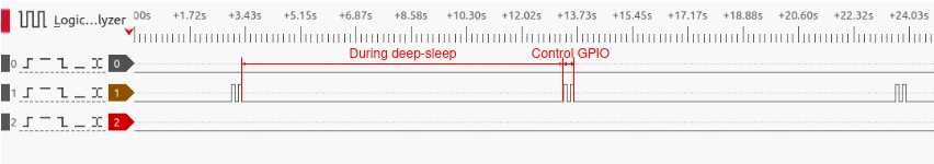
UART#
Here is an example demonstrating how to send the string “Hello world” via the UART interface using LL-layer functions within a wake stub application. See the ESP32-C6 TRM UART Section for UART details.
Detailed steps:
Include low-level header files and define a log color macro.
Details
#include "hal/gpio_ll.h"
#include "hal/uart_ll.h"
#include "esp_private/uart_share_hw_ctrl.h"
#include "esp_rom_gpio.h"

#define RTC_LOG_COLOR_GREEN(fmt) "\033[0;32m" fmt "\033[0m"
Define UART-related configuration macros.
Details
#define UART_TOUT_THRESH_DEFAULT 10
#define UART_BAUD_RATE 9600
#define TXD_PIN 4
#define RXD_PIN 5
Obtain hardware instances and define transmission data.
Details
RTC_DATA_ATTR gpio_dev_t *  gpio_dev = GPIO_LL_GET_HW(GPIO_PORT_0);
RTC_DATA_ATTR uart_dev_t *  uart_dev =UART_LL_GET_HW(UART_NUM_1);

const RTC_DATA_ATTR char * const ch = "Hello world";
const RTC_DATA_ATTR uint8_t * write_buf = (const uint8_t *) ch;
Define a function to calculate the total number of bits required to transmit one UART symbol.
Details
uint8_t uart_get_symb_len(uart_dev_t * dev)
{
    uint8_t symbol_len = 1; // number of bits per symbol including start
    uart_parity_t parity_mode;
    uart_stop_bits_t stop_bit;
    uart_word_length_t data_bit;
    uart_ll_get_data_bit_num(dev, &data_bit);
    uart_ll_get_stop_bits(dev, &stop_bit);
    uart_ll_get_parity(dev, &parity_mode);
    symbol_len += (data_bit < UART_DATA_BITS_MAX) ? (uint8_t)data_bit + 5 : 8;
    symbol_len += (stop_bit > UART_STOP_BITS_1) ? 2 : 1;
    symbol_len += (parity_mode > UART_PARITY_DISABLE) ? 1 : 0;
    return symbol_len;
}
The following code is performed inside the esp_wake_func() function:
- Initialize UART hardware and configure its parameters.
Details
```c
uart_ll_enable_bus_clock(UART_NUM_1, true);
uart_ll_reset_register(UART_NUM_1);
uart_ll_sclk_enable(uart_dev);

uart_ll_set_mode(uart_dev, UART_MODE_UART);

uart_ll_set_parity(uart_dev, UART_PARITY_DISABLE);
uart_ll_set_data_bit_num(uart_dev, UART_DATA_8_BITS);
uart_ll_set_stop_bits(uart_dev, UART_STOP_BITS_1);
uart_ll_set_tx_idle_num(uart_dev, 0);
uart_ll_set_hw_flow_ctrl(uart_dev, UART_HW_FLOWCTRL_DISABLE, 0);

uart_ll_set_sclk(uart_dev, SOC_MOD_CLK_XTAL);
uart_ll_set_baudrate(uart_dev, UART_BAUD_RATE, 40000000);

uart_ll_rxfifo_rst(uart_dev);
uart_ll_txfifo_rst(uart_dev);
```
Configure the TX pin for UART output functionality.
Details
gpio_ll_func_sel(gpio_dev, TXD_PIN, PIN_FUNC_GPIO);
esp_rom_gpio_connect_out_signal(TXD_PIN, U1TXD_OUT_IDX, false, false);
Transmit data.
Details
ESP_RTC_LOGI(RTC_LOG_COLOR_GREEN("UART TX_TASK: Sending: %s"), write_buf);
uart_ll_write_txfifo(uart_dev, write_buf, 12);
while(!uart_ll_is_tx_idle(uart_dev));
To conveniently test the wake stub, we implemented a UART receive task that continuously runs to receive data sent by the transmit task. The receiver uses the UART driver, and the main function code is shown below. For more information, refer to Universal Asynchronous Receiver/Transmitter (UART).
uart_rxtask_main.c
#include "freertos/FreeRTOS.h"
#include "freertos/task.h"
#include "esp_system.h"
#include "esp_log.h"
#include "driver/uart.h"
#include "string.h"
#include "driver/gpio.h"

static const int RX_BUF_SIZE = 1024;

#define TXD_PIN (CONFIG_EXAMPLE_UART_TXD)
#define RXD_PIN (CONFIG_EXAMPLE_UART_RXD)

void init(void)
{
    const uart_config_t uart_config = {
        .baud_rate = 9600,
        .data_bits = UART_DATA_8_BITS,
        .parity = UART_PARITY_DISABLE,
        .stop_bits = UART_STOP_BITS_1,
        .flow_ctrl = UART_HW_FLOWCTRL_DISABLE,
        .source_clk = SOC_MOD_CLK_XTAL,
    };

    uart_driver_install(UART_NUM_1, RX_BUF_SIZE * 2, 0, 0, NULL, 0);
    uart_param_config(UART_NUM_1, &uart_config);
    uart_set_pin(UART_NUM_1, TXD_PIN, RXD_PIN, UART_PIN_NO_CHANGE, UART_PIN_NO_CHANGE);
}

static void rx_task(void *arg)
{
    static const char *RX_TASK_TAG = "RX_TASK";
    esp_log_level_set(RX_TASK_TAG, ESP_LOG_INFO);
    uint8_t* data = (uint8_t*) malloc(RX_BUF_SIZE + 1);
    while (1) {
        uart_flush_input(UART_NUM_1);
        const int rxBytes = uart_read_bytes(UART_NUM_1, data, RX_BUF_SIZE, 1000 / portTICK_PERIOD_MS);
        if (rxBytes > 0) {
            data[rxBytes] = 0;
            ESP_LOGI(RX_TASK_TAG, "Received: %s", data);
        }
    }
    free(data);
}

void app_main(void)
{
    init();
    xTaskCreate(rx_task, "uart_rx_task", 3072, NULL, configMAX_PRIORITIES - 1, NULL);
}
Flash the program to the ESP32-C6 acting as the transceiver:
Flash the program to the ESP32-C6 acting as the receiver:
I2C#
Here is an example demonstrating how to send the string “Hello world” via the I2C interface using LL-layer functions within a wake stub application. See the ESP32-C6 TRM I2C Section for I2C details.
Detailed steps:
Include low-level header files and define a log color macro.
Details
#include "esp_rom_gpio.h"
#include "hal/gpio_ll.h"

#include "hal/i2c_types.h"
#include "hal/i2c_ll.h"
#include "hal/clk_tree_ll.h"
#include "soc/periph_defs.h"
#include "hal/clk_gate_ll.h"
#include "soc/soc.h"
#include "soc/i2c_reg.h"

#define RTC_LOG_COLOR_GREEN(fmt) "\033[0;32m" fmt "\033[0m"
Configure I2C-related macros.
Details
#define I2C_MASTER_NUM I2C_NUM_0
#define I2C_SDA 5
#define I2C_SCL 4
#define FILTER_NUM 0
#define SCL_SPEED_HZ 100000
#define SCL_WAIT_US 20000
Obtain hardware instances, the 7-bit I2C slave address, and the data to be sent.
Details
RTC_DATA_ATTR gpio_dev_t *gpio_dev = GPIO_LL_GET_HW(GPIO_PORT_0);
RTC_DATA_ATTR i2c_dev_t *i2c_dev = I2C_LL_GET_HW(0);

const RTC_DATA_ATTR char * const ch = "Hello world";
const RTC_DATA_ATTR uint8_t * write_buf = (const uint8_t *) ch;

#define I2C_SLAVE_ADDR_7BIT 0x34
RTC_DATA_ATTR uint8_t i2c_slave_write_addr = (I2C_SLAVE_ADDR_7BIT << 1) | 0;
The following code is performed inside the esp_wake_func() function:
Enable and reset the I2C peripheral’s bus and controller clocks.
Details
i2c_ll_enable_bus_clock(0, true);
i2c_ll_reset_register(0);
i2c_ll_enable_controller_clock(i2c_dev, true);
Configure SDA and SCL GPIO pins.
Details
// SDA pin configurations
gpio_ll_set_level(gpio_dev, I2C_SDA, 1);
gpio_ll_input_enable(gpio_dev, I2C_SDA);
gpio_ll_od_enable(gpio_dev, I2C_SDA);
gpio_ll_pullup_en(gpio_dev, I2C_SDA);
gpio_ll_pulldown_dis(gpio_dev, I2C_SDA);
gpio_ll_func_sel(gpio_dev, I2C_SDA, PIN_FUNC_GPIO);
esp_rom_gpio_connect_out_signal(I2C_SDA, I2CEXT0_SDA_OUT_IDX, 0, 0);
esp_rom_gpio_connect_in_signal(I2C_SDA, I2CEXT0_SDA_IN_IDX, 0);

// SCL pin configurations
gpio_ll_set_level(gpio_dev, I2C_SCL, 1);
gpio_ll_input_enable(gpio_dev, I2C_SCL);
gpio_ll_od_enable(gpio_dev, I2C_SCL);
gpio_ll_pullup_en(gpio_dev, I2C_SCL);
gpio_ll_pulldown_dis(gpio_dev, I2C_SCL);
gpio_ll_func_sel(gpio_dev, I2C_SCL, PIN_FUNC_GPIO);
esp_rom_gpio_connect_out_signal(I2C_SCL, I2CEXT0_SCL_OUT_IDX, 0, 0);
esp_rom_gpio_connect_in_signal(I2C_SCL, I2CEXT0_SCL_IN_IDX, 0);
Configure I2C master mode and control parameters.
Details
i2c_ll_set_mode(i2c_dev, I2C_BUS_MODE_MASTER);
i2c_ll_enable_pins_open_drain(i2c_dev, true);
i2c_ll_enable_arbitration(i2c_dev, false);
i2c_ll_master_rx_full_ack_level(i2c_dev, false);
i2c_ll_set_data_mode(i2c_dev, I2C_DATA_MODE_MSB_FIRST, I2C_DATA_MODE_MSB_FIRST);//MSB
i2c_ll_txfifo_rst(i2c_dev);
i2c_ll_rxfifo_rst(i2c_dev);
i2c_ll_update(i2c_dev);
Configure the I2C bus clock.
Details
i2c_ll_set_source_clk(i2c_dev, SOC_MOD_CLK_XTAL);
i2c_ll_master_set_filter(i2c_dev, FILTER_NUM);

i2c_hal_clk_config_t clk_cal;
i2c_ll_master_cal_bus_clk(clk_ll_xtal_load_freq_mhz() * MHZ, SCL_SPEED_HZ, &clk_cal);
i2c_ll_master_set_bus_timing(i2c_dev, &clk_cal);
uint32_t reg_val = i2c_ll_calculate_timeout_us_to_reg_val(clk_ll_xtal_load_freq_mhz() * MHZ, SCL_WAIT_US);
i2c_ll_set_tout(i2c_dev, reg_val);
i2c_ll_master_set_fractional_divider(i2c_dev, 0, 0);
i2c_ll_update(i2c_dev);
Construct the I2C hardware command sequence.
Details
i2c_ll_hw_cmd_t hw_cmd[] = {
    {
        .op_code = I2C_LL_CMD_RESTART,
    },
    {
        .op_code = I2C_LL_CMD_WRITE,
        .ack_en = true,
        .byte_num = 13, //The data num is 12, the address num is 1
    },
    {
        .op_code = I2C_LL_CMD_STOP,
    }
};
Execute the I2C data transmission process.
Details
while(i2c_ll_is_bus_busy(i2c_dev)){}

i2c_ll_txfifo_rst(i2c_dev);
i2c_ll_rxfifo_rst(i2c_dev);

ESP_RTC_LOGI(RTC_LOG_COLOR_GREEN("i2c_master: Sending: %s"), write_buf);

i2c_ll_master_write_cmd_reg(i2c_dev, hw_cmd[0], 0);
i2c_ll_write_txfifo(i2c_dev, &i2c_slave_write_addr, 1);
i2c_ll_write_txfifo(i2c_dev, write_buf, 12);
i2c_ll_master_write_cmd_reg(i2c_dev, hw_cmd[1], 1);
i2c_ll_master_write_cmd_reg(i2c_dev, hw_cmd[2], 2);
i2c_ll_update(i2c_dev);
i2c_ll_start_trans(i2c_dev);
To conveniently test the wake stub, we implemented an I2C slave task that continuously runs to receive data sent by the I2C master task. The slave uses the I2C_slave driver, and the main function code is shown below. For more information, refer to Inter-Integrated Circuit (I2C).
i2c_slave_device_main.c
#include "freertos/FreeRTOS.h"
#include "freertos/task.h"
#include "esp_log.h"
#include "driver/i2c_slave.h"
#include "esp_rom_sys.h"


#define I2C_SLAVE_PORT         0
#define I2C_SLAVE_SDA_IO       5
#define I2C_SLAVE_SCL_IO       4
#define I2C_SLAVE_ADDR_7BIT   0x34
#define I2C_SLAVE_BUF_LEN      128

static const char *TAG = "i2c_slave";

static QueueHandle_t event_queue;
static uint8_t *temp_data = NULL;
static size_t temp_len = 0;
static i2c_slave_dev_handle_t handle = NULL;

typedef enum {
    I2C_SLAVE_EVT_RX,
    I2C_SLAVE_EVT_TX,
} i2c_slave_event_t;

static IRAM_ATTR bool i2c_slave_request_cb(i2c_slave_dev_handle_t i2c_slave,
                                          const i2c_slave_request_event_data_t *evt_data, void *arg)
{
    BaseType_t xTaskWoken = pdFALSE;
    i2c_slave_event_t evt = I2C_SLAVE_EVT_TX;
    xQueueSendFromISR(event_queue, &evt, &xTaskWoken);
    return xTaskWoken;
}

static IRAM_ATTR bool i2c_slave_receive_cb(i2c_slave_dev_handle_t i2c_slave,
                                          const i2c_slave_rx_done_event_data_t *evt_data, void *arg)
{
    BaseType_t xTaskWoken = pdFALSE;
    i2c_slave_event_t evt = I2C_SLAVE_EVT_RX;
    memcpy(temp_data, evt_data->buffer, evt_data->length);
    temp_len = evt_data->length;
    xQueueSendFromISR(event_queue, &evt, &xTaskWoken);
    return xTaskWoken;
}

static void i2c_slave_task(void *arg)
{
    i2c_slave_event_t evt;
    uint8_t tx_data[I2C_SLAVE_BUF_LEN];
    size_t tx_len;

    while (1) {
        if (xQueueReceive(event_queue, &evt, portMAX_DELAY) == pdTRUE) {
            if (evt == I2C_SLAVE_EVT_RX) {
                ESP_LOGI(TAG, "Received %d bytes from master:", temp_len);
                ESP_LOGI(TAG, "%s ", (char*) temp_data);
            } else if (evt == I2C_SLAVE_EVT_TX) {
                for (int i = 0; i < I2C_SLAVE_BUF_LEN; i++) {
                    tx_data[i] = i;
                }
                tx_len = I2C_SLAVE_BUF_LEN;
                uint32_t written = 0;
                esp_err_t err = i2c_slave_write(handle, tx_data, tx_len, &written, 1000);
                ESP_LOGI(TAG, "Master read request: wrote %d bytes (err=0x%x)", written, err);
            }
        }
    }
}

void i2c_slave_start(void)
{
    esp_err_t ret;
    temp_data = heap_caps_malloc(I2C_SLAVE_BUF_LEN, MALLOC_CAP_DEFAULT);
    assert(temp_data);

    event_queue = xQueueCreate(4, sizeof(i2c_slave_event_t));
    assert(event_queue);

    i2c_slave_config_t i2c_slv_config = {
        .i2c_port = I2C_SLAVE_PORT,
        .clk_source = I2C_CLK_SRC_DEFAULT,
        .scl_io_num = I2C_SLAVE_SCL_IO,
        .sda_io_num = I2C_SLAVE_SDA_IO,
        .slave_addr = I2C_SLAVE_ADDR_7BIT,
        .send_buf_depth = I2C_SLAVE_BUF_LEN,
        .receive_buf_depth = I2C_SLAVE_BUF_LEN,
        .flags.enable_internal_pullup = true,
        .addr_bit_len = I2C_ADDR_BIT_LEN_7,
    };

    ret = i2c_new_slave_device(&i2c_slv_config, &handle);
    ESP_LOGI(TAG, "i2c_new_slave_device: %s", esp_err_to_name(ret));

    i2c_slave_event_callbacks_t cbs = {
        .on_receive = i2c_slave_receive_cb,
        .on_request = i2c_slave_request_cb,
    };

    ret = i2c_slave_register_event_callbacks(handle, &cbs, NULL);
    ESP_LOGI(TAG, "i2c_slave_register_event_callbacks: %s", esp_err_to_name(ret));

    xTaskCreate(i2c_slave_task, "i2c_slave_task", 2048, NULL, 10, NULL);
}

void app_main(void)
{
    i2c_slave_start();

    while (1) {
        vTaskDelay(pdMS_TO_TICKS(1000));
    }
}
Flash the program to the ESP32-C6 acting as the I2C master:
Set CONFIG_I2C_ENABLE_SLAVE_DRIVER_VERSION_2 = y and flash the program to the ESP32-C6 acting as the I2C slave:
SPI#
Here is an example demonstrating how to send the string “Hello world” via the SPI interface using LL-layer functions within a wake stub application. See the ESP32-C6 TRM SPI Section for SPI details.
Detailed steps:
Include low-level header files and define a log color macro.
Details
#include "hal/gpio_ll.h"
#include "esp_rom_gpio.h"

#include "hal/spi_types.h"
#include "hal/spi_ll.h"
#include "soc/clk_tree_defs.h"
#include "hal/clk_tree_ll.h"

#define RTC_LOG_COLOR_GREEN(fmt) "\033[0;32m" fmt "\033[0m"
Configure SPI-related macros.
Details
#define SPI_MISO        5
#define SPI_MOSI        4
#define SPI_CLK         6
#define SPI_CS          12

#define clock_speed_hz  1 * 1000 * 1000  // 1 MHz
#define duty_cycle_pos  128

#define CS_PIN_ID       0
#define SPI_MODE        0
#define TX_BITLEN       88
#define CMD_BITLEN      0
#define ADDR_BITLEN     0
Obtain hardware instances.
Details
RTC_DATA_ATTR gpio_dev_t *  gpio_dev = GPIO_LL_GET_HW(GPIO_PORT_0);
RTC_DATA_ATTR spi_dev_t * spi_dev = SPI_LL_GET_HW(SPI2_HOST);
Set the transmit content.
Details
const RTC_DATA_ATTR char * const ch = "Hello world";
const RTC_DATA_ATTR uint8_t * write_buf = (const uint8_t *) ch;
The following code is performed inside the esp_wake_func() function:
Initialize the SPI bus and configure pin functions.
Details
spi_ll_enable_bus_clock(SPI2_HOST, true);
spi_ll_reset_register(SPI2_HOST);

gpio_ll_input_enable(gpio_dev, SPI_MOSI);
esp_rom_gpio_connect_in_signal(SPI_MOSI, FSPID_IN_IDX, false);
esp_rom_gpio_connect_out_signal(SPI_MOSI, FSPID_OUT_IDX, false, false);
gpio_ll_func_sel(gpio_dev, SPI_MOSI, PIN_FUNC_GPIO);

gpio_ll_input_enable(gpio_dev, SPI_MISO);
esp_rom_gpio_connect_in_signal(SPI_MISO, FSPIQ_IN_IDX, false);
esp_rom_gpio_connect_out_signal(SPI_MISO, FSPIQ_OUT_IDX, false, false);
gpio_ll_func_sel(gpio_dev, SPI_MISO, PIN_FUNC_GPIO);

esp_rom_gpio_connect_out_signal(SPI_CLK, FSPICLK_OUT_IDX, false, false);
gpio_ll_func_sel(gpio_dev, SPI_CLK, PIN_FUNC_GPIO);
SPI controller initialization and configuration.
- Enable clock and initialize the SPI controller.
Details
periph_ll_enable_clk_clear_rst(PERIPH_SPI2_MODULE); spi_ll_reset_register(SPI2_HOST); spi_ll_master_init(spi_dev); spi_ll_enable_int(spi_dev); spi_ll_set_int_stat(spi_dev); spi_ll_set_mosi_delay(spi_dev, 0, 0); spi_ll_apply_config(spi_dev);- Configure SPI master clock.
Details
uint32_t clock_source_hz = clk_ll_xtal_load_freq_mhz() * MHZ;; spi_ll_clock_val_t reg_val; spi_ll_master_cal_clock(clock_source_hz, clock_speed_hz, duty_cycle_pos, ®_val); spi_ll_master_set_clock_by_reg(spi_dev, ®_val);- Configure CS pin.
Details
esp_rom_gpio_connect_out_signal(SPI_CS, FSPICS0_OUT_IDX, false, false); gpio_ll_input_enable(gpio_dev, SPI_CS); esp_rom_gpio_connect_in_signal(SPI_CS, FSPICS0_IN_IDX, false); gpio_ll_func_sel(gpio_dev, SPI_CS, PIN_FUNC_GPIO);- Configure transfer parameters.
Details
spi_ll_master_set_pos_cs(spi_dev, CS_PIN_ID, false);
spi_ll_master_set_rx_timing_mode(spi_dev, false);
spi_ll_set_rx_lsbfirst(spi_dev, false);
spi_ll_set_tx_lsbfirst(spi_dev, false);
spi_ll_master_set_mode(spi_dev, 0); // SPI mode 0
spi_ll_set_half_duplex(spi_dev, false);
spi_ll_set_sio_mode(spi_dev, false);
spi_ll_master_set_cs_setup(spi_dev, 0); // disable the setup phase
spi_ll_master_set_cs_hold(spi_dev, 1);
spi_ll_master_select_cs(spi_dev, CS_PIN_ID);
spi_ll_set_clk_source(spi_dev, SOC_MOD_CLK_XTAL);
Configure and send SPI data.
Details
spi_line_mode_t line_mode = {
  .cmd_lines = 1,
  .addr_lines = 1,
  .data_lines = 1
};
spi_ll_master_set_line_mode(spi_dev, line_mode);
spi_ll_set_dummy(spi_dev, 0); // disable the dummy phase

spi_ll_set_mosi_bitlen(spi_dev, TX_BITLEN);
spi_ll_set_addr_bitlen(spi_dev, ADDR_BITLEN);
spi_ll_set_command_bitlen(spi_dev, CMD_BITLEN);
spi_ll_set_command(spi_dev, 0, CMD_BITLEN, false);
spi_ll_set_address(spi_dev, 0, ADDR_BITLEN, false);

spi_ll_master_keep_cs(spi_dev, 0); // don't keep CS activated

ESP_RTC_LOGI(RTC_LOG_COLOR_GREEN("SPI_MASTER: Sending: %s"), write_buf);

spi_ll_write_buffer(spi_dev, write_buf, TX_BITLEN);
spi_ll_enable_mosi(spi_dev, true);

spi_ll_apply_config(spi_dev);
spi_ll_user_start(spi_dev);
while(!spi_ll_usr_is_done(spi_dev));
To conveniently test the wake stub, we implemented a SPI slave task that continuously runs to receive data sent by the transmit task. The receiver uses the SPI driver, and the main function code is shown below. For more information, refer to SPI Slave Driver.
Slave_app_main.c
#include <stdio.h>
#include <string.h>
#include "driver/spi_slave.h"
#include "driver/gpio.h"
#include "esp_log.h"

#define PIN_NUM_MOSI 4
#define PIN_NUM_MISO 5
#define PIN_NUM_CLK  6
#define PIN_NUM_CS   12

#define RCV_BUF_SIZE 64

static const char *TAG = "SPI_SLAVE";

void app_main(void)
{
    esp_err_t ret;

    spi_bus_config_t buscfg = {
        .mosi_io_num = PIN_NUM_MOSI,
        .miso_io_num = PIN_NUM_MISO,
        .sclk_io_num = PIN_NUM_CLK,
        .quadwp_io_num = -1,
        .quadhd_io_num = -1,
        .max_transfer_sz = RCV_BUF_SIZE,
        .flags = SPICOMMON_BUSFLAG_SLAVE | SPICOMMON_BUSFLAG_GPIO_PINS,
    };

    spi_slave_interface_config_t slvcfg = {
        .spics_io_num = PIN_NUM_CS,
        .flags = 0,
        .queue_size = 3,
        .mode = 0,
    };

    gpio_set_pull_mode(PIN_NUM_MOSI, GPIO_PULLUP_ONLY);
    gpio_set_pull_mode(PIN_NUM_CLK, GPIO_PULLUP_ONLY);
    gpio_set_pull_mode(PIN_NUM_CS, GPIO_PULLUP_ONLY);

    ret = spi_slave_initialize(SPI2_HOST, &buscfg, &slvcfg, SPI_DMA_CH_AUTO);
    if (ret != ESP_OK) {
        ESP_LOGE(TAG, "Failed to initialize SPI slave: %s", esp_err_to_name(ret));
        return;
    }

    uint8_t recv_buf[RCV_BUF_SIZE] = {0};
    spi_slave_transaction_t trans = {
        .length = RCV_BUF_SIZE * 8,
        .tx_buffer = NULL,
        .rx_buffer = recv_buf,
    };

    ESP_LOGI(TAG, "SPI slave ready to receive...");

    while (1) {
        memset(recv_buf, 0, sizeof(recv_buf));
        ret = spi_slave_transmit(SPI2_HOST, &trans, portMAX_DELAY);
        if (ret == ESP_OK) {
            ESP_LOGI(TAG, "Received: %s", (char *)recv_buf);
        } else {
            ESP_LOGE(TAG, "SPI transmit failed: %s", esp_err_to_name(ret));
        }
    }

    spi_slave_free(SPI2_HOST);
}
Flash the program to the ESP32-C6 acting as the SPI master:
Flash the program to the ESP32-C6 acting as the SPI slave:
Wrapping up#
Now you should know the basics of what the Deep-sleep wake stub application can do and how to begin developing with it.
For more Deep-sleep insights and updates, be sure to check back at the developer portal!