

Introduction#
General Purpose Input/Output (GPIO) pins are fundamental interfaces on Espressif SoCs, enabling direct interaction with the physical world. They allow your device to read signals from sensors and switches, control LEDs and motors, and connect to a wide range of peripherals. Mastering GPIO usage is essential for building responsive and reliable embedded systems.
As with most modern architectures, these pins can be mapped to different functions. A GPIO can operate as a general-purpose digital pin or be assigned to a digital peripheral like SPI or UART. This configuration is handled transparently by the internal GPIO matrix.
As their name implies, GPIOs can function as both inputs and outputs. In this first article, we’ll focus on configuring and controlling an output GPIO pin.
Output configuration#
All modern microcontrollers offer several ways to configure an output GPIO. We will discuss the two main options:
- Push-pull
- Open-drain
Push-pull#
The push pull configuration is shown in Fig.1.
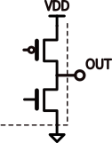
Fig.1 - Push pull configuration
In this configuration, the output level is always well-defined because the internal MOSFETs actively drive the pin both high and low. The GPIO can both source current (when driving high) and sink current (when driving low), making it the most common configuration for general-purpose digital outputs.
Open Drain#
The open drain configuration is shown in Fig.2. Fig.2 - Open drain configurations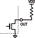
In this configuration, the GPIO only sinks current and must be connected to an external power supply through a resistor. The output can actively drive a strong LOW, while the HIGH level is provided by the pull-up resistor.
Historically, this configuration was used to interface with higher voltages. An open-drain output allowed a low-voltage logic device to safely control or signal a higher-voltage system without ever driving that higher voltage internally. The device would only pull the line LOW, while the external pull-up defined the HIGH level.
Since Espressif GPIOs have a maximum output voltage of 3.6 V, this configuration is now mainly used to share a bus among multiple devices, as in I²C communication. You can connect many output drain pins to the same node, while you can’t do the same with push-pull outputs.
Maximum output current#
When you drive a pin HIGH or LOW, and the pin is connected to a load, you must supply enough current to maintain the desired logic level. Consider a simple 330 Ω resistor connected to your GPIO:

Fig. 3 - GPIO output load
For Espressif modules, a digital value of one corresponds to a voltage of 3.3 V. To maintain this voltage across a 330 Ω resistor, the SoC must supply 10 mA. In Espressif documentation, the maximum output current is referred to as drive capability. You can configure this value for each GPIO, and the default setting is 20 mA. This means you cannot reliably drive a load with an equivalent resistance lower than 165 Ω.
Espressif GPIO peripheral#
To use any peripheral, you should follow three steps:
- Include the peripheral driver.
- Configure the peripheral.
- Use the peripheral.
Let’s look at each of these steps for the GPIO peripheral.
Include the peripheral driver#
The instructions for including a library can be found in the ESP-IDF Programming Guide, under the relevant peripheral API reference, in the Header File section.
For example, the GPIO API reference shows that the GPIO peripheral is managed through the driver/gpio.h library, which must be included as:
#include "driver/gpio.h"
If you are using it inside the main component, which by default already depends on all ESP-IDF components, no additional actions are needed. For other components, you must add one of the following to its CMakeLists.txt:S
REQUIRES esp_driver_gpio
or
PRIV_REQUIRES esp_driver_gpio
Configure the library#
To use a GPIO as an output, we need to specify:
- Direction (output)
- Mode (push-pull)
In Espressif, both direction and mode are managed through the gpio_mode_t enum and are therefore set together using the gpio_set_direction function.
| Mode name | gpio_mode_t | Description |
|---|---|---|
| Disable | GPIO_MODE_DISABLE | Disables the GPIO completely. Both input and output functions are turned off, leaving the pin inactive. |
| Input | GPIO_MODE_INPUT | Configures the GPIO as input only, allowing it to read external logic levels without driving the pin. |
| Output (Push-Pull) | GPIO_MODE_OUTPUT | Configures the GPIO as output only in push-pull mode, actively driving both HIGH and LOW levels. |
| Output (Open-Drain) | GPIO_MODE_OUTPUT_OD | Configures the GPIO as output only in open-drain mode. The pin can pull the line LOW and requires a pull-up for HIGH. |
| Input / Output (Open-Drain) | GPIO_MODE_INPUT_OUTPUT_OD | Enables both input and output in open-drain mode, typically used for shared or bidirectional lines such as I²C. |
| Input / Output (Push-Pull) | GPIO_MODE_INPUT_OUTPUT | Enables both input and output in push-pull mode, useful when the pin must both drive and read a signal. |
For example, to set GPIO5 as a push-pull output we can use
gpio_set_direction(5,GPIO_MODE_OUTPUT);
gpio_od_enable and gpio_od_disable, which enable and disable open-drain mode respectively. The complete list of available APIs can be found in the GPIO section of the programming guide’s API referenceCheck the configuration#
To inspect the configuration of all GPIOs, ESP-IDF provides the function gpio_dump_io_configuration.
If we only call gpio_set_direction(5, GPIO_MODE_OUTPUT);, the dump for GPIO 5 looks like this:
IO[5] -
  Pullup: 0, Pulldown: 0, DriveCap: 2
  InputEn: 0, OutputEn: [periph_sig_ctrl], OpenDrain: 0
  FuncSel: 1 (GPIO)
  GPIO Matrix SigOut ID: 256 (simple GPIO output)
  SleepSelEn: 0
From this output, you can see:
DriveCap– shows the configured drive capabilityOpenDrain: 0– open-drain mode is disabled meaning that the pin is set up for standard GPIO output
A complete GPIO configuration dump is shown below.
Show full GPIO dump
================IO DUMP Start================
IO[0] -
  Pullup: 0, Pulldown: 0, DriveCap: 2
  InputEn: 0, OutputEn: [periph_sig_ctrl], OpenDrain: 0
  FuncSel: 1 (GPIO)
  GPIO Matrix SigOut ID: 256 (simple GPIO output)
  SleepSelEn: 0

IO[1] -
  Pullup: 0, Pulldown: 0, DriveCap: 2
  InputEn: 0, OutputEn: [periph_sig_ctrl], OpenDrain: 0
  FuncSel: 1 (GPIO)
  GPIO Matrix SigOut ID: 256 (simple GPIO output)
  SleepSelEn: 0

IO[2] -
  Pullup: 0, Pulldown: 0, DriveCap: 2
  InputEn: 0, OutputEn: [periph_sig_ctrl], OpenDrain: 0
  FuncSel: 1 (GPIO)
  GPIO Matrix SigOut ID: 256 (simple GPIO output)
  SleepSelEn: 0

IO[3] -
  Pullup: 0, Pulldown: 0, DriveCap: 2
  InputEn: 1, OutputEn: [periph_sig_ctrl], OpenDrain: 0
  FuncSel: 0 (IOMUX)
  SleepSelEn: 0

IO[4] -
  Pullup: 0, Pulldown: 0, DriveCap: 2
  InputEn: 1, OutputEn: [periph_sig_ctrl], OpenDrain: 0
  FuncSel: 0 (IOMUX)
  SleepSelEn: 0

IO[5] -
  Pullup: 0, Pulldown: 0, DriveCap: 2
  InputEn: 0, OutputEn: [periph_sig_ctrl], OpenDrain: 0
  FuncSel: 1 (GPIO)
  GPIO Matrix SigOut ID: 256 (simple GPIO output)
  SleepSelEn: 0

IO[6] -
  Pullup: 0, Pulldown: 0, DriveCap: 2
  InputEn: 1, OutputEn: [periph_sig_ctrl], OpenDrain: 0
  FuncSel: 0 (IOMUX)
  SleepSelEn: 0

IO[7] -
  Pullup: 0, Pulldown: 0, DriveCap: 2
  InputEn: 1, OutputEn: [periph_sig_ctrl], OpenDrain: 0
  FuncSel: 1 (GPIO)
  GPIO Matrix SigOut ID: 256 (simple GPIO output)
  GPIO Matrix SigIn ID: (simple GPIO input)
  SleepSelEn: 0

IO[8] -
  Pullup: 0, Pulldown: 0, DriveCap: 2
  InputEn: 1, OutputEn: [periph_sig_ctrl], OpenDrain: 0
  FuncSel: 1 (GPIO)
  GPIO Matrix SigOut ID: 256 (simple GPIO output)
  GPIO Matrix SigIn ID: (simple GPIO input)
  SleepSelEn: 0

IO[9] -
  Pullup: 1, Pulldown: 0, DriveCap: 2
  InputEn: 1, OutputEn: [periph_sig_ctrl], OpenDrain: 0
  FuncSel: 1 (GPIO)
  GPIO Matrix SigOut ID: 256 (simple GPIO output)
  GPIO Matrix SigIn ID: (simple GPIO input)
  SleepSelEn: 0

IO[10] -
  Pullup: 1, Pulldown: 0, DriveCap: 2
  InputEn: 1, OutputEn: [periph_sig_ctrl], OpenDrain: 0
  FuncSel: 0 (IOMUX)
  SleepSelEn: 0

IO[11] -
  Pullup: 1, Pulldown: 0, DriveCap: 2
  InputEn: 1, OutputEn: [periph_sig_ctrl], OpenDrain: 0
  FuncSel: 0 (IOMUX)
  SleepSelEn: 0

IO[12] -
  Pullup: 0, Pulldown: 0, DriveCap: 3
  InputEn: 1, OutputEn: [periph_sig_ctrl], OpenDrain: 0
  FuncSel: 1 (GPIO)
  GPIO Matrix SigOut ID: 256 (simple GPIO output)
  GPIO Matrix SigIn ID: (simple GPIO input)
  SleepSelEn: 0

IO[13] -
  Pullup: 0, Pulldown: 0, DriveCap: 3
  InputEn: 1, OutputEn: [periph_sig_ctrl], OpenDrain: 0
  FuncSel: 1 (GPIO)
  GPIO Matrix SigOut ID: 256 (simple GPIO output)
  GPIO Matrix SigIn ID: (simple GPIO input)
  SleepSelEn: 0

IO[14] -
  Pullup: 1, Pulldown: 0, DriveCap: 2
  InputEn: 1, OutputEn: [periph_sig_ctrl], OpenDrain: 0
  FuncSel: 1 (GPIO)
  GPIO Matrix SigOut ID: 256 (simple GPIO output)
  GPIO Matrix SigIn ID: (simple GPIO input)
  SleepSelEn: 0

IO[15] **RESERVED** -
  Pullup: 1, Pulldown: 0, DriveCap: 1
  InputEn: 1, OutputEn: [periph_sig_ctrl], OpenDrain: 0
  FuncSel: 0 (IOMUX)
  SleepSelEn: 0

IO[16] **RESERVED** -
  Pullup: 1, Pulldown: 0, DriveCap: 1
  InputEn: 1, OutputEn: [periph_sig_ctrl], OpenDrain: 0
  FuncSel: 0 (IOMUX)
  SleepSelEn: 0

IO[17] **RESERVED** -
  Pullup: 1, Pulldown: 0, DriveCap: 1
  InputEn: 1, OutputEn: [periph_sig_ctrl], OpenDrain: 0
  FuncSel: 1 (GPIO)
  GPIO Matrix SigOut ID: 256 (simple GPIO output)
  GPIO Matrix SigIn ID: (simple GPIO input)
  SleepSelEn: 0

IO[18] -
  Pullup: 0, Pulldown: 0, DriveCap: 2
  InputEn: 0, OutputEn: [periph_sig_ctrl], OpenDrain: 0
  FuncSel: 1 (GPIO)
  GPIO Matrix SigOut ID: 256 (simple GPIO output)
  SleepSelEn: 0

IO[19] **RESERVED** -
  Pullup: 1, Pulldown: 0, DriveCap: 1
  InputEn: 1, OutputEn: [periph_sig_ctrl], OpenDrain: 0
  FuncSel: 1 (GPIO)
  GPIO Matrix SigOut ID: 256 (simple GPIO output)
  GPIO Matrix SigIn ID: (simple GPIO input)
  SleepSelEn: 0

IO[20] **RESERVED** -
  Pullup: 1, Pulldown: 0, DriveCap: 1
  InputEn: 1, OutputEn: [periph_sig_ctrl], OpenDrain: 0
  FuncSel: 0 (IOMUX)
  SleepSelEn: 0

IO[21] **RESERVED** -
  Pullup: 1, Pulldown: 0, DriveCap: 1
  InputEn: 1, OutputEn: [periph_sig_ctrl], OpenDrain: 0
  FuncSel: 0 (IOMUX)
  SleepSelEn: 0

IO[22] -
  Pullup: 0, Pulldown: 0, DriveCap: 2
  InputEn: 1, OutputEn: [periph_sig_ctrl], OpenDrain: 0
  FuncSel: 1 (GPIO)
  GPIO Matrix SigOut ID: 256 (simple GPIO output)
  GPIO Matrix SigIn ID: (simple GPIO input)
  SleepSelEn: 0

IO[23] -
  Pullup: 0, Pulldown: 0, DriveCap: 2
  InputEn: 1, OutputEn: [periph_sig_ctrl], OpenDrain: 0
  FuncSel: 1 (GPIO)
  GPIO Matrix SigOut ID: 256 (simple GPIO output)
  GPIO Matrix SigIn ID: (simple GPIO input)
  SleepSelEn: 0

IO[24] -
  Pullup: 0, Pulldown: 0, DriveCap: 2
  InputEn: 0, OutputEn: [periph_sig_ctrl], OpenDrain: 0
  FuncSel: 1 (GPIO)
  GPIO Matrix SigOut ID: 256 (simple GPIO output)
  SleepSelEn: 0

IO[25] -
  Pullup: 0, Pulldown: 0, DriveCap: 2
  InputEn: 1, OutputEn: [periph_sig_ctrl], OpenDrain: 0
  FuncSel: 1 (GPIO)
  GPIO Matrix SigOut ID: 256 (simple GPIO output)
  GPIO Matrix SigIn ID: (simple GPIO input)
  SleepSelEn: 0

IO[26] -
  Pullup: 0, Pulldown: 0, DriveCap: 2
  InputEn: 1, OutputEn: [periph_sig_ctrl], OpenDrain: 0
  FuncSel: 1 (GPIO)
  GPIO Matrix SigOut ID: 256 (simple GPIO output)
  GPIO Matrix SigIn ID: (simple GPIO input)
  SleepSelEn: 0

IO[27] -
  Pullup: 0, Pulldown: 0, DriveCap: 2
  InputEn: 1, OutputEn: [periph_sig_ctrl], OpenDrain: 0
  FuncSel: 1 (GPIO)
  GPIO Matrix SigOut ID: 256 (simple GPIO output)
  GPIO Matrix SigIn ID: (simple GPIO input)
  SleepSelEn: 0

IO[28] -
  Pullup: 0, Pulldown: 0, DriveCap: 2
  InputEn: 1, OutputEn: [periph_sig_ctrl], OpenDrain: 0
  FuncSel: 1 (GPIO)
  GPIO Matrix SigOut ID: 256 (simple GPIO output)
  GPIO Matrix SigIn ID: (simple GPIO input)
  SleepSelEn: 0

IO[29] -
  Pullup: 0, Pulldown: 0, DriveCap: 2
  InputEn: 0, OutputEn: [periph_sig_ctrl], OpenDrain: 0
  FuncSel: 1 (GPIO)
  GPIO Matrix SigOut ID: 256 (simple GPIO output)
  SleepSelEn: 0

=================IO DUMP End=================
Use the library#
For an output GPIO, the only required function is to set the output level to low or high. The function is gpio_set_level.
gpio_set_level(5, 0); // GPIO 5 set to 0
gpio_set_level(5, 1); // GPIO 5 set to 1
Choose the right pin#
Espressif modules include multiple pins labelled GPIOs. Before using a GPIO in your application, make sure the pin:
- Does not function as a strapping pin
- Supports output, not just input
- Is not internally connected to the module’s flash or PSRAM
You can verify this in the Pin Overview cheatsheet. For more details, find a chip datasheet for your chip and go to the Pins section.
Practical example#
To demonstrate this, we will develop a simple blinking application from scratch. In this example, we will use an ESP32-C61-DevKitC-1, but any Espressif module and EVK can be used. We will use VS Code and ESP-IDF Extension for VS Code.
Connect the LED#
Most modern Espressif DevKits do not have a simple onboard LED (also called a GPIO LED) and typically feature RGB LEDs instead. For this reason, we need to connect an external LED to a GPIO. We will use GPIO5.
The connection is shown in Fig.4. Fig.4 - Connections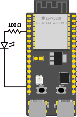
Create a new empty project#
- Open VS Code
> ESP-IDF: Create a New Empty Project→ name itled-test- Click on the pop-up asking to open the new project
Include the library#
In main.c, include the libraries for GPIO, FreeRTOS (for the delay), and the logging library for output. You can remove stdio.h since its functions will not be used.
#include "esp_log.h"
#include "driver/gpio.h"
#include "freertos/FreeRTOS.h"
#include "freertos/task.h"
Configure the library#
For this simple application, we only need to set GPIO5 as an output. To keep things organized, we will define its value after the includes. In the same place, we also define the TAG string for logging. For more on tags and logging, make sure to check out the article ESP-IDF tutorial series: Logging.
#define LED_GPIO 5
static const char *TAG = "LED_TEST";
In the app_main function we can configure it as:
gpio_set_direction(LED_GPIO,GPIO_MODE_OUTPUT);
Use the library#
Next, we need to create the loop that will handle the LED driving.
 uint32_t led_state = 0; // keep track of the led state

    while (1) {
            // Toggle the LED state
            led_state = !led_state;
            // Drive the led
            gpio_set_level(LED_GPIO, led_state);
            // Feedback on terminal
            ESP_LOGI(TAG,"Status:%s", led_state? "ON":"OFF");
            // Delay of 0.5s
            vTaskDelay(pdMS_TO_TICKS(500));
    }
In the log we used the C ternary opeartor to show the string “ON” and “OFF” instead of one and zero.
vTaskDelay function takes the number of ticks as its argument. To work with milliseconds instead of ticks, we can use the pdMS_TO_TICKS macro, which converts a given millisecond value to the corresponding number of ticks.Example code
main.c
#include "esp_log.h"
#include "driver/gpio.h"
#include "freertos/FreeRTOS.h"
#include "freertos/task.h"

#define LED_GPIO 5
static const char * TAG = "LED_TEST";

void app_main(void)
{

    ESP_LOGI(TAG,"** GPIO get started tutorial ** ");
    gpio_set_direction(LED_GPIO,GPIO_MODE_OUTPUT);

    uint32_t led_state = 0;

    while (1) {
            // Toggle the LED state
            led_state = !led_state;
            // Drive the led
            gpio_set_level(LED_GPIO, led_state);
            // Feedback on terminal
            ESP_LOGI(TAG,"Status:%s", led_state? "ON":"OFF");
            // Delay of 0.5s
            vTaskDelay(pdMS_TO_TICKS(500));
        }
}
Conclusion#
In this article, we went through a practical introduction to GPIO programming. We explored how to configure and control an output GPIO on Espressif SoCs, set up a blinking LED, and used FreeRTOS for timing.
In the next article, we will explore how to use a GPIO as an input.
Go to Part 2