


Imagine this scenario: a device is already deployed and running normally when a security review uncovers a bootloader vulnerability. Fixing it requires updating the bootloader on the device in the field.
Although this may look like a standard OTA update, replacing the bootloader is significantly riskier than updating an application. If the bootloader becomes invalid because of an interrupted write, an incomplete image, or a verification failure, the device may no longer boot.
The recovery bootloader feature addresses this risk by keeping an additional known-good bootloader image at a separate flash location. If the bootloader cannot be loaded, the recovery image is used instead.
This article explains how to perform bootloader OTA updates while minimizing the risk of leaving a device unbootable. The examples use ESP-IDF v6.1 and ESP32-C5, but the same general approach applies to other supported chips.
Application OTA vs. bootloader OTA#
Application OTA updates normally use multiple application slots. A new image is written to an inactive slot while the currently running application remains unchanged. If the new image fails validation or does not boot successfully, the system can return to the previous application.
The bootloader does not provide the same protection by default. A typical flash layout contains only one bootloader image. Once that image is erased, partially overwritten, or corrupted, there is no valid bootloader to continue the boot process. The device is effectively bricked until it can be reflashed via a physical connection.
Bootloader updates have historically been uncommon because the bootloader is intentionally kept small and changes infrequently. However, the bootloader may contain a vulnerability which can therefore require updating the bootloader on already deployed devices.
Recovery also requires support from the chip’s ROM bootloader. For this reason, recovery bootloader functionality is available only on chips that implement the corresponding ROM-level fallback mechanism.
Bootloader update approaches#
There are two general approaches to updating the bootloader:
- Recovery-assisted update: Before replacing the primary bootloader, the application writes a known-good bootloader image to the recovery bootloader location. If the primary bootloader becomes invalid, the ROM bootloader can load the recovery image. This is the recommended approach, which this article covers in detail.
- Direct update: The application writes the new image directly over the primary bootloader without preparing a recovery image. This approach has a higher risk of leaving the device unbootable. It may be the only available option on chips without recovery bootloader support.
Key terms#
Before diving in, it helps to have a clear picture of the boot stages, and how they relate to each other.
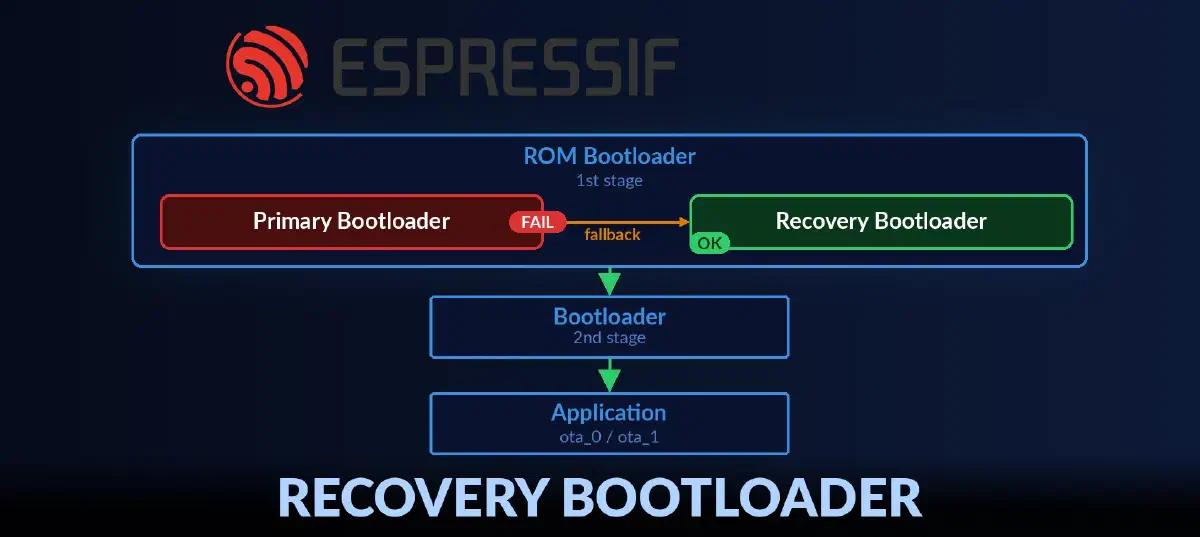
1st stage bootloader or ROM bootloader is the very first code that runs after the chip powers up. It lives in read-only memory baked into the silicon — it cannot be changed. Its job is simple: find a valid 2nd stage bootloader image in flash, verify it, load it, and hand over control.
2nd stage bootloader or simply bootloader is the ESP-IDF bootloader binary. It is responsible for reading the partition table, selecting an application partition, verifying it, loading it, and launching the application. This is the image that bootloader OTA update replaces.
Primary bootloader is called the bootloader which is located at the regular bootloader offset in flash (often 0x0000, 0x1000, or 0x2000).
Recovery bootloader is a known-good copy of the bootloader stored at a different flash offset. The ROM bootloader uses it only if it cannot load the primary bootloader. In normal operation, the recovery bootloader is not used.
Normal boot flow#
When the primary bootloader is present and valid, the boot flow looks like this:
Power-up
  └─► ROM bootloader              (1st stage bootloader)
        └─► Primary bootloader    (2nd stage bootloader)
              └─► Application
Recovery bootloader flow#
When the primary bootloader is missing or corrupted, the ROM bootloader falls back to the recovery bootloader:
Power-up
  └─► ROM bootloader
        ├─► Primary bootloader — FAIL
        └─► Recovery bootloader
              └─► Application
The address of the recovery bootloader is stored on chip in eFuse. eFuse is a one-time programmable memory on the chip. Once a bit burns (0 -> 1), it cannot be changed.
Which chips support recovery bootloader#
The recovery bootloader feature is available only on chips whose ROM bootloader supports it. In ESP-IDF this is exposed through the CONFIG_BOOTLOADER_RECOVERY_ENABLE Kconfig option. You can find this option in menuconfig under Bootloader config -> Recovery Bootloader and Rollback. At the time of writing, the list of supported chips is:
| Chip | CONFIG_BOOTLOADER_RECOVERY_ENABLE availability |
|---|---|
| ESP32-C5 | ESP-IDF v5.5+ |
| ESP32-C61 | ESP-IDF v5.5+ |
| ESP32-P4 (chip version >= 3.0) | ESP-IDF v5.5+ |
| ESP32-S31 | ESP-IDF v6.1+ |
Setting up the recovery bootloader#
After confirming target support and enabling the CONFIG_BOOTLOADER_RECOVERY_ENABLE Kconfig option, the next step is setting up the recovery bootloader. Start by reviewing your partition layout and reserving a suitable free flash region for the recovery bootloader.
1. Choosing a place for the recovery bootloader#
To choose a location for the recovery bootloader, first estimate the maximum bootloader image size your layout allows.
In ESP-IDF, that limit is defined by the region between the primary bootloader offset and the partition table offset. CONFIG_PARTITION_TABLE_OFFSET does not directly define the bootloader image size, but it defines the upper boundary of this region.
The recovery bootloader image is of the same size as the primary bootloader image. The maximum bootloader size is calculated as CONFIG_PARTITION_TABLE_OFFSET - CONFIG_BOOTLOADER_OFFSET_IN_FLASH. For example, if the partition table starts at 0x8000 and the primary bootloader is at 0x1000, the maximum bootloader size is 0x7000 bytes.
After choosing the recovery location, set the CONFIG_BOOTLOADER_RECOVERY_OFFSET Kconfig option to that address. The same address must also be programmed into eFuse, which will be done later in the article. This is the only address the ROM bootloader needs to know to find the recovery bootloader.
You can also define this region explicitly adding the bootloader recovery entry (recovery_bloader) in the partition table. This is mainly for consistency and documentation of the flash layout.
2. Partition table layout#
ESP-IDF documents partition table types and subtypes in the official guide: ESP-IDF Partition Tables. The recommended partition table layout is:
# ESP-IDF Partition Table
# Name,           Type,            SubType,  Offset,  Size,     Flags
bootloader,       bootloader,      primary,  N/A,     N/A,
partition_table,  partition_table, primary,  N/A,     N/A,
ota_data,         data,            ota,      ,        0x2000,
nvs,              data,            nvs,      ,        0x6000,
phy_init,         data,            phy,      ,        0x1000,
ota_0,            app,             ota_0,    ,        1M,
ota_1,            app,             ota_1,    ,        1M,
recovery_bloader, bootloader,      recovery, N/A,     N/A,
Compared with the default ESP-IDF partition table, this layout adds explicit bootloader and partition_table entries. This makes the flash map easier to review and fully documents the whole flash layout. Run idf.py partition-table to view the partition table with offsets and sizes.
Note:
- If a product is already deployed and its existing table does not include a bootloader partition entry you still can utilize the bootloader recovery functionality. There is a dedicated API that can help to add missing partitions to the partition table at runtime,
N/Ais a special value that indicates the partition tool will fill this field automatically deriving the values from the configuration for certain partition types,- Between the primary bootloader and primary partition table no other partitions should be placed. As this region is dedicated for primary bootloader only and defines the maximum bootloader size. The recovery bootloader should be placed in a separate region.
3. Programming the recovery bootloader eFuse#
You can program the recovery bootloader eFuse in two ways:
- During application runtime: call the following API:
esp_efuse_set_recovery_bootloader_offset(CONFIG_BOOTLOADER_RECOVERY_OFFSET); - From the host machine: use
espefuse.py:espefuse --port /dev/ttyUSB0 burn_efuse RECOVERY_BOOTLOADER_FLASH_SECTOR 0x3F0
The recovery bootloader eFuse field is represented as a sector number, not a raw byte address. To convert the recovery bootloader offset to a sector number, divide the offset by the flash sector size (0x1000). For example, if the recovery bootloader offset is 0x3F0000, the corresponding eFuse value is 0x3F0000 / 0x1000 = 0x3F0.
RECOVERY_BOOTLOADER_FLASH_SECTOR = CONFIG_BOOTLOADER_RECOVERY_OFFSET / 0x1000
Bootloader OTA update#
The bootloader OTA update flow is similar to the application OTA update flow. The main difference is that you need to prepare bootloader partitions and eFuse before starting the update.
1. Get partition handles for primary and recovery bootloader#
If the partition table already includes explicit bootloader entries, you can use the following code to get partition handles for both primary and recovery bootloader regions. We need these handles to copy the bootloader images between partitions.
const esp_partition_t *primary_bootloader = esp_partition_find_first(
  ESP_PARTITION_TYPE_BOOTLOADER,
  ESP_PARTITION_SUBTYPE_BOOTLOADER_PRIMARY,
  NULL);

const esp_partition_t *recovery_bootloader = esp_partition_find_first(
  ESP_PARTITION_TYPE_BOOTLOADER,
  ESP_PARTITION_SUBTYPE_BOOTLOADER_RECOVERY,
  NULL);
If the partition table does not include explicit bootloader entries, for products already deployed, you can use the following code to register equivalent regions at runtime:
const esp_partition_t *primary_bootloader;
esp_partition_register_external(NULL,
  ESP_PRIMARY_BOOTLOADER_OFFSET,
  ESP_BOOTLOADER_SIZE,
  "PrimaryBTLDR",
  ESP_PARTITION_TYPE_BOOTLOADER,
  ESP_PARTITION_SUBTYPE_BOOTLOADER_PRIMARY,
  &primary_bootloader);

const esp_partition_t *recovery_bootloader;
esp_partition_register_external(NULL,
  CONFIG_BOOTLOADER_RECOVERY_OFFSET,
  ESP_BOOTLOADER_SIZE,
  "RecoveryBTLDR",
  ESP_PARTITION_TYPE_BOOTLOADER,
  ESP_PARTITION_SUBTYPE_BOOTLOADER_RECOVERY,
  &recovery_bootloader);
2. Burn recovery bootloader offset in eFuse#
Burn the recovery bootloader offset into eFuse. If this eFuse field is not set, this API will burn the value. If the eFuse is already set and has the same value, this API does nothing. But if it has a different value, this API will return an error.
esp_efuse_set_recovery_bootloader_offset(CONFIG_BOOTLOADER_RECOVERY_OFFSET);3. Create a known-good recovery bootloader backup#
Before starting the OTA update, back up the primary bootloader to the recovery partition. Because the device just booted from it, the image is known to work. If the device was booted from the recovery bootloader, the recovery bootloader already holds a valid image — skip the copy and proceed to the download step.
if (esp_rom_get_bootloader_offset() == ESP_PRIMARY_BOOTLOADER_OFFSET) {
  // Primary was used to boot the device.
  ESP_LOGI(TAG, "Backing up primary bootloader to recovery partition.");
  esp_partition_copy(recovery_bootloader, 0, primary_bootloader, 0, primary_bootloader->size);
} else {
  // The recovery bootloader already holds a valid image.
  ESP_LOGW(TAG, "Recovery bootloader was used to boot the device");
  ESP_LOGI(TAG, "Skipping backup, recovery bootloader already holds a valid image.");
}
4. Download new bootloader image into an inactive OTA slot#
Use inactive OTA slot (ota_0 or ota_1) to download new bootloader image. This is the same flow as for application OTA updates. The new bootloader image is downloaded into this staging partition, which will be copied to the primary bootloader partition only after successful verification. The high-level OTA helper used here is documented in ESP HTTPS OTA.
esp_https_ota_config_t *ota_config;

// free app ota partition will be used to store the new bootloader image
const esp_partition_t *free_ota_slot = esp_ota_get_next_update_partition(NULL);
ota_config->partition.staging = free_ota_slot;

// The target for the OTA update.
ota_config->partition.final = primary_bootloader;

esp_https_ota(ota_config);
esp_partition_copy(primary_bootloader, 0, free_ota_slot, 0, primary_bootloader->size);
Once the new bootloader image is verified, copy it to the primary bootloader partition. This is the critical moment in the update, because the primary bootloader is erased and then rewritten in place. If a power loss or other failure happens during this step, the primary bootloader will be left in a corrupted state. In that case, the recovery bootloader will be used on the next boot.
5. ROM bootloader behavior#
After restart, the ROM bootloader tries to load and verify the primary bootloader. If it succeeds, it jumps to it immediately. If it fails, the ROM reads the RECOVERY_BOOTLOADER_FLASH_SECTOR eFuse. If the eFuse holds 0 (not provisioned) or 0xFFF (permanently disabled), the ROM skips recovery and retries the primary — looping indefinitely. Any other value is a valid sector offset: the ROM loads the recovery bootloader from that address and jumps to it if loading succeeds. If recovery loading also fails, the ROM retries the primary, again indefinitely.
This is why a working recovery image must be flashed before the primary is erased. If both are broken at the same time, there is no escape from the infinite loop.
When the recovery path happens, the ROM log will look like this:
ESP-ROM:esp32c5-eco2-20250121
Build:Jan 21 2025
rst:0x1 (POWERON),boot:0x18 (SPI_FAST_FLASH_BOOT)
invalid header: 0xffffffff
invalid header: 0xffffffff
invalid header: 0xffffffff
PRIMARY - FAIL
Loading RECOVERY Bootloader...
SPI mode:DIO, clock div:1
load:0x408556b0,len:0x17cc
load:0x4084bba0,len:0xdac
load:0x4084e5a0,len:0x3140
entry 0x4084bbaa

I (46) boot: ESP-IDF ... 2nd stage bootloader
The ROM bootloader does the same secure boot verification on the recovery bootloader as it does on the primary.
6. Application behavior after bootloader OTA#
At every startup, check which bootloader was used to boot the device:
- Primary bootloader is active — the new bootloader loaded successfully.
- Recovery bootloader is active — the primary bootloader failed. The device recovered gracefully. Now in the application, you need to restore the primary bootloader from the known-good recovery image so the next OTA cycle starts from a clean state.
if (esp_rom_get_bootloader_offset() == ESP_PRIMARY_BOOTLOADER_OFFSET) {
  ESP_LOGI(TAG, "Primary bootloader is active — OTA succeeded.");
} else {
  ESP_LOGW(TAG, "Recovery bootloader is active — primary OTA failed, restoring primary from recovery.");
  esp_partition_copy(primary_bootloader, 0, recovery_bootloader, 0, primary_bootloader->size);
}
This check-and-act pattern is the recommended way to close the bootloader OTA loop and prepare the device for the next OTA cycle.
Anti-rollback#
ESP-IDF supports anti-rollback for the bootloader using the same mechanism it uses for applications. Each image carries a secure_version field in its header. The chip has a matching eFuse field that stores the minimum accepted version. Bootloader loads only images whose secure_version is equal to or higher than the value stored in eFuse. Once a new image is confirmed to be working, the eFuse value can be advanced to that image’s secure_version — after which any image with a lower version is rejected unconditionally, even if it is otherwise valid and signed. This prevents an attacker from downgrading the bootloader to a known vulnerable version.
Application and bootloader anti-rollback use separate secure_version eFuse fields and are checked at different stages: the 1st stage bootloader checks the 2nd stage bootloader version, and the 2nd stage bootloader checks the application version.
The bootloader secure_version field is part of the Bootloader Image Format. Bootloader anti-rollback is available only on some chips where recovery bootloader is supported, please check whether CONFIG_BOOTLOADER_ANTI_ROLLBACK_ENABLE is available for your target.
Enabling anti-rollback for the bootloader is optional. It is controlled by the CONFIG_BOOTLOADER_ANTI_ROLLBACK_ENABLE Kconfig option. When enabled, CONFIG_BOOTLOADER_SECURE_VERSION sets the secure_version written into the bootloader image header at build time.
How the eFuse value advances depends on BOOTLOADER_ANTI_ROLLBACK_UPDATE_IN_ROM: if set, the ROM bootloader burns a higher secure version automatically after successful verification; if not set, the application must advance it explicitly. The application-managed pattern is shown below.
esp_bootloader_desc_t primary_bootloader_desc;
size_t efuse_secure_version = 0;

if (esp_rom_get_bootloader_offset() == ESP_PRIMARY_BOOTLOADER_OFFSET) {

  // Get the primary bootloader description, which includes the secure_version field.
  esp_ota_get_bootloader_description(NULL, &primary_bootloader_desc);

  // Read the eFuse secure_version
  esp_efuse_read_field_cnt(ESP_EFUSE_BOOTLOADER_ANTI_ROLLBACK_SECURE_VERSION, &efuse_secure_version);

  // Advance the secure_version in eFuse. It prevents loading older bootloaders.
  if (primary_bootloader_desc.secure_version > efuse_secure_version) {
    size_t diff = primary_bootloader_desc.secure_version - efuse_secure_version;
    esp_efuse_write_field_cnt(ESP_EFUSE_BOOTLOADER_ANTI_ROLLBACK_SECURE_VERSION, diff);
  }
}
The BOOTLOADER_ANTI_ROLLBACK_SECURE_VERSION field uses monotonic bit-count encoding: each increment burns one additional bit to 1. Most chips allocate 4 bits, giving a maximum of 4 increments (0x0 → 0x1 → 0x3 → 0x7 → 0xF). Before shipping, check the exact bit width for your chip and plan the versioning scheme to stay within that budget.
The table below illustrates how the bootloader versioning works in practice. In the table, Ver means esp_bootloader_desc_t.version, sec_ver means the image secure_version, and eFuse min means BOOTLOADER_ANTI_ROLLBACK_SECURE_VERSION.
| Ver | sec_ver | eFuse min | Meaning |
|---|---|---|---|
1 | 0 | 0 | Initial production image. Anti-rollback not used yet. |
2 | 0 | 0 | New bootloader build, but no security fix. Older image is still accepted. |
3 | 1 | 0 | Security-fix build. Accepted because 1 >= 0. |
3 | 1 | 1 | Same image after eFuse advance. Any image with secure_version = 0 is now rejected. |
4 | 2 | 1 | Later security-fix build. Accepted because 2 >= 1. |
4 | 2 | 2 | eFuse advanced again. Any image with secure_version < 2 is rejected. |
Bootloader OTA without recovery bootloader#
Without a recovery bootloader, overwriting the primary bootloader has no automatic safety net. A power failure or invalid image during the flash operation leaves the device permanently unable to boot — recovery requires physical access via JTAG or a serial programmer. Only proceed if you have an alternative rescue path and accept the risk.
The update flow is identical to Bootloader OTA update with steps 2 and 3 omitted — there is no recovery partition to provision and no known-good backup to place there. The esp_partition_copy() call at the end of step 4 is the critical moment: if it fails, the device is bricked. Do it when you make sure the power supply is stable.
A complete example is available in the partitions_ota example.
Conclusion#
You now have a complete picture of bootloader OTA updates: the safe path using the recovery bootloader for chips with ROM support, and the riskier direct flash write for chips without it. The recovery bootloader path is strongly recommended. For a complete working example, see the partitions_ota example in the ESP-IDF repository.