



Introduction#
Pulse Width Modulation (PWM) is a technique that encodes an analog signal by varying the width of digital pulses. The key advantage of PWM is that it allows you to generate any average voltage between 0 and the supply peak using nothing more than a standard digital output. This makes it an indispensable technique for controlling lights and motors, and a practical solution for applications ranging from straightforward LED dimming to more sophisticated analog signal generation.
Espressif devices include two kinds of PWM peripherals:
ledc: a simple PWM peripheral designed for controlling LEDs and lights.mcpwm: a fully featured motor control PWM peripheral with complementary outputs, programmable dead times, fault detection inputs, and three-phase output support. It is designed for driving motors and other applications that require precise timing control and signal synchronization.
We will focus on the first one, ledc, which is the most common choice for lighting applications.
This article is divided into three parts:
- PWM signal overview: we’ll explore what a PWM signal is and the names of its parts.
- Espressif LEDC peripheral: we’ll generate a PWM signal using an Espressif DevKit
- PWM to DC conversion: we’ll see how to extract the DC value and how to design an appropriate filter
PWM signal overview#
Before starting, let’s understand what a PWM signal is.
A PWM signal is a rectangular wave with two voltage levels: 0 and \(V_{on}\). The signal remains at \(V_{on}\) for a duration of \(T_\text{on}\), and at 0 for \(T_\text{off}\). The time between two consecutive rising edges defines the switching period, \(T_s\), which is the sum of \(T_\text{on}\) and \(T_\text{off}\)
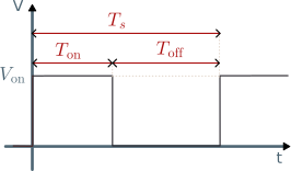
PWM signal
The most important parameter of a PWM signal is the duty cycle, usually called D.
$$ D=\frac{T_{on}}{T_{s}} $$
Since \(T_{on}\) cannot exceed \(T_s\), the duty cycle ranges from 0 to 1 and is typically expressed as a percentage.
The second most important parameter is the switching frequency \(f_s\), which is the inverse of the switching period.
$$ f_s=\frac{1}{T_s} $$
Average voltage#
To find the average value (\(\bar{V}_\text{PWM}\)) of a PWM signal that switches between 0 and \(V_\text{on}\), we integrate over one switching period:
$$ \bar{V}_\text{PWM}=\frac{1}{T_s}\left( T_\text{on} \cdot V_\text{on} + T_\text{off} \cdot 0 \right) = D V_\text{on} $$
The result shows that the average voltage is directly proportional to the duty cycle \(D\).
By varying \(D\) from 0 to 1, you can generate any average voltage between 0 and \(V_{on}\) using only a digital output. This is the most important feature of a PWM signal.
PWM signal generation#
Let’s first look at the analog way to generate a PWM signal before showing how to do it digitally.
Analog PWM signal generation#
The most common way to generate a PWM signal is by using a triangular or sawtooth wave and feeding it into a comparator that compares it with a DC signal.
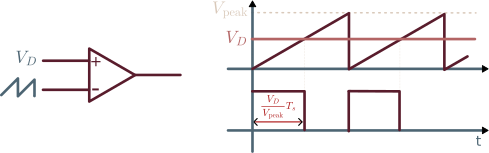
PWM analog generation
When the control voltage \(V_D\) equals the peak value \(V_\text{peak}\), the comparator output stays high for the entire period, so \(T_\text{on}=T_s\). When \(V_D\) is zero, the output never goes high, so \(T_\text{on}=0\). In general, the pulse width scales linearly with the control voltage:
$$ T_\text{on}=\frac{V_D}{V_\text{peak}}T_s $$
Comparing this with the definition of the duty cycle \(D=\frac{T_\text{on}}{T_s}\), we obtain:
$$ D=\frac{V_D}{V_\text{peak}} $$
We can achieve the same result digitally with just a timer and an internal comparator.
Digital PWM signal generation#
To generate a PWM signal digitally, we need to feed a clock at a frequency \( f_\text{clock}=\frac{1}{T_\text{clock}} \) to a digital counter and compare its \(N_\text{bit}\) count (\(n_\text{count}\)) with a digital value \(N_D\).
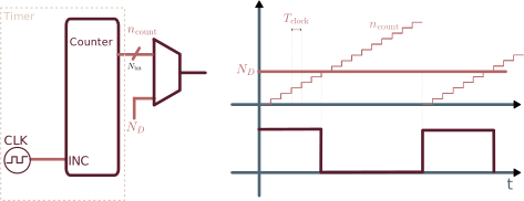
PWM digital generation
With this setup, you can increase the resolution of the duty cycle by increasing the size of the counter (\(N_\text{bit}\), i.e. the bit size of \(N_D\))
If you choose, for example, a 12-bit size, the resolution of the duty cycle becomes \(\frac{1}{2^{N_\text{bit}}} = \frac{1}{4096}\simeq 0.024 \)% .
Note that the PWM switching frequency \(f_s\) decreases by the same factor:
$$ f_{s} = \frac{f_\text{clock}}{2^{N_\text{bit}}} $$
Lower frequencies mean you need bigger filters to remove the harmonics, as we will see in a later section.
Espressif LEDC peripheral#
The LEDC PWM peripheral in Espressif devices has two parts: the timer and the channel.
You can use the same timer as a source for different channels. If two channels share the same timer, they share the same bit resolution and PWM frequency.
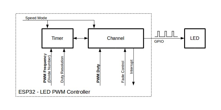
Espressif LEDC PWM peripheral
The following sections cover the most important parts of the LEDC peripheral:
- LEDC timer configuration
- LEDC channel configuration
- LEDC duty cycle setting
LEDC timer configuration#
The timer is configured by populating the ledc_timer_config_t struct and passing it to ledc_timer_config().
// Configure the LEDC timer
    ledc_timer_config_t ledc_timer = {
        .speed_mode      = LEDC_MODE,
        .duty_resolution = LEDC_DUTY_RES,
        .timer_num       = LEDC_TIMER,
        .freq_hz         = LEDC_FREQUENCY,
        .clk_cfg         = LEDC_AUTO_CLK,
    };

    ledc_timer_config(&ledc_timer);
The struct fields have the following meaning:
speed_modeSelects the speed mode of the LEDC timer group. For all chips but ESP32, the only option is
LEDC_LOW_SPEED_MODE.duty_resolutionThis enum sets the resolution of the PWM duty cycle in bits. For example
LEDC_TIMER_13_BITgives a duty range[0, 8191](\(2^{13}\) steps)timer_numThis enum lets you select which hardware timer to configure. Typically, there are 4 timers:
LEDC_TIMER_0throughLEDC_TIMER_3.freq_hzThe desired PWM output frequency in Hz (e.g.,
5000for 5 kHz).As we’ve seen before, the maximum PWM frequency depends on the clock frequency and duty resolution.
$$ f_s=\frac{f_\text{clock}}{2^{N_\text{bit}}} $$
clk_cfgSelects the source clock for the timer. Available options vary by chip. Here we use
LEDC_AUTO_CLK, which automatically selects the clock source based on the given resolution and frequency parameters when initializing the timer. A common frequency value is $$ f_\text{clock}=4\text{ MHz} $$
LEDC channel configuration#
To configure the channel, pass the following structure:
   // Configure the LEDC channel
    ledc_channel_config_t ledc_channel = {
        .speed_mode = LEDC_MODE,
        .channel    = LEDC_CHANNEL,
        .timer_sel  = LEDC_TIMER,
        .gpio_num   = LEDC_OUTPUT_IO,
        .duty       = 0,   // Start at 0% duty cycle
        .hpoint     = 0,
    };

    ledc_channel_config(&ledc_channel);
The struct fields have the following meaning:
speed_modeSame as above.
channelThis enum selects which LEDC channel to use. Espressif devices typically have between 6 and 8 channels.
timer_selSame as
timer_numabove.gpio_numThe GPIO pin number where the PWM signal will be output. In this example, we set:
#define LEDC_OUTPUT_IO (25)dutySets the initial duty cycle of the PWM signal. Setting it to
0means 0% duty cycle (signal always low). The maximum value (full duty) equals \(2^{N_\text{bit}}\).We can later change the duty cycle with
ledc_set_duty.hpointThe “high point” value defines the counter value at which the PWM output goes high within a PWM cycle. Setting it to
0is the standard/default behavior, meaning the output goes high at the start of each cycle.TipIf you have two channels driven by the same timer, you can use this value to create a phase-shifted version of the PWM signal. This is useful in several power conversion scenarios, but that’s outside the scope of this article.
LEDC duty cycle setting#
To set the duty cycle at runtime, call the function:
int duty_cycle;
esp_err_t ret = ledc_set_duty(LEDC_MODE, LEDC_CHANNEL, duty_cycle);
with duty_cycle between 0 and \(2^{N_\text{bit}}\). Since the duty cycle is usually defined between 0 and 1, we will create a wrapper function:
#define LEDC_FS  (1 << LEDC_DUTY_RES) // Full scale 2^13

esp_err_t ledc_set_duty_cycle(float duty){
    esp_err_t ret = ledc_set_duty(LEDC_MODE, LEDC_CHANNEL, (int) (duty*LEDC_FS));
    if(ret != ESP_OK){
        return ret;
    }
    ret = ledc_update_duty(LEDC_MODE, LEDC_CHANNEL);
    return ret;
}
Putting all together#
In the following example, we will configure the LEDC timer and channel and measure the output.
To make the code cleaner, we wrap the configuration of both the timer and the channel inside a ledc_init function.
We use GPIO 25 to output the PWM signal.
Example full code
#include <stdio.h>
#include "driver/ledc.h"
#include "esp_err.h"
#include "esp_log.h"

#define LEDC_TIMER        LEDC_TIMER_0
#define LEDC_MODE         LEDC_LOW_SPEED_MODE
#define LEDC_OUTPUT_IO    (25)               // Output GPIO pin
#define LEDC_CHANNEL      LEDC_CHANNEL_0
#define LEDC_DUTY_RES     LEDC_TIMER_13_BIT // 13-bit resolution
#define LEDC_FS           (1 << LEDC_DUTY_RES) // Full scale 2^13
#define LEDC_DUTY         ((LEDC_FS * 75) / 100) // 75% duty cycle
#define LEDC_FREQUENCY    (4000)            // 4 kHz


const static char * TAG = "main";

static void ledc_init(void)
{
    // Configure the LEDC timer
    ledc_timer_config_t ledc_timer = {
        .speed_mode      = LEDC_MODE,
        .duty_resolution = LEDC_DUTY_RES,
        .timer_num       = LEDC_TIMER,
        .freq_hz         = LEDC_FREQUENCY,
        .clk_cfg         = LEDC_AUTO_CLK,
    };
    ESP_ERROR_CHECK(ledc_timer_config(&ledc_timer));

    // Configure the LEDC channel
    ledc_channel_config_t ledc_channel = {
        .speed_mode = LEDC_MODE,
        .channel    = LEDC_CHANNEL,
        .timer_sel  = LEDC_TIMER,
        .gpio_num   = LEDC_OUTPUT_IO,
        .duty       = LEDC_DUTY,
        .hpoint     = 0,
    };
    ESP_ERROR_CHECK(ledc_channel_config(&ledc_channel));
}

esp_err_t ledc_set_duty_cycle(float duty){
    esp_err_t ret = ledc_set_duty(LEDC_MODE, LEDC_CHANNEL, (int) (duty*LEDC_FS));
    if(ret != ESP_OK){
        return ret;
    }
    ret = ledc_update_duty(LEDC_MODE, LEDC_CHANNEL);
    return ret;
}

void app_main(void)
{
    ESP_LOGI(TAG, "Initializing LED, setting duty cycle to %d%%", (int)(100*(float)LEDC_DUTY/(float)LEDC_FS));
    ledc_init();
}
Example output#
If we now connect an oscilloscope to GPIO 25, we will see the PWM output waveform.
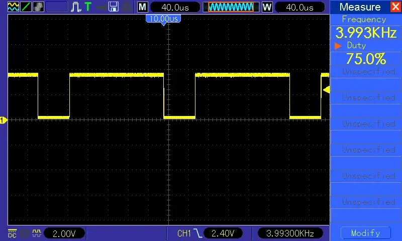
PWM output
As you can see, the frequency is 4 kHz and the duty cycle is a perfect 75%.
PWM to DC conversion#
In the previous sections we established that the average value of a PWM signal is:
$$ \bar{V}_\text{PWM}=D V_{on} $$
This average, however, is only the DC component of the signal. A PWM waveform is far from a clean DC voltage: it also contains a series of AC components that we need to account for.
Harmonics#
A PWM signal is periodic, so it can be decomposed into its frequency components using the Fourier series. The DC term is the average value we already computed, and the remaining terms are the harmonics.
For our purposes, the key takeaway is that these harmonics appear at the switching frequency \(f_s\) and at its integer multiples \(2f_s, 3f_s, \dots\).
If you are curious about the math, the amplitude of the \(j\)-th harmonic has the following closed form:
$$ \frac{a_j}{V_+} = \frac{2}{j\pi}\sin(j\pi D) $$
The figure below shows the resulting spectrum for a duty cycle of \(D = 0.25\).
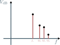
PWM signal spectrum for D=0.25
If we want to generate a clean DC signal from this switching wave, we need to remove the harmonics. We need to attenuate the signal components at frequency \(f_s\) and higher, while keeping the DC value unchanged. We can achieve this by using a simple resistor-capacitor (RC) filter.
RC filter design#
The simplest filter we can use is the following.
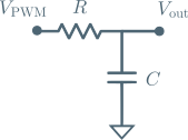
RC filter
If we connect the PWM signal (\(V_\text{PWM}\)) to this network and extract the output signal (\(V_\text{out}\)), the network attenuates the amplitude depending on the frequency.
This filter acts as a simple voltage divider:
$$ V_\text{out} = \frac{Z_C}{Z_R+Z_C}V_\text{PWM} $$
The resistor impedance (\(Z_R\)) does not depend on frequency and is always equal to the resistance value (\(R\)), while the capacitor impedance amplitude is:
$$ |Z_C| = \left|\frac{1}{2\pi f C}\right| $$
The higher the frequency, the lower the impedance offered by the capacitor. As a result, the voltage divider yields a lower output.
If we plot the attenuation in dB as a function of the frequency on a log scale, we get the asymptotic Bode plot of the attenuation:
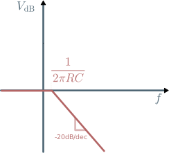
Filter Bode plot
What’s important to notice is that this filter does not significantly alter frequencies lower than the cutoff frequency (\(\frac{1}{2\pi R C}\)), while reducing everything above it by about 20 dB per decade. This means that for each 10x increase in frequency, the amplitude is reduced by a factor of 10 (20 dB).
So if we design the filter to have a cutoff frequency of 1/10 of \(f_s\), the first harmonic will be reduced by a factor of 10. If we set it to 1/100 of \(f_s\), the reduction will be 100.
RC filter comparison#
To see how the filter design affects the output voltage, let’s design two filters (A and B) at 1/10 and 1/100 of the \(f_\text{PWM}\) respectively.
| Filter | Cut-off frequency | R | C |
|---|---|---|---|
| A | 400 Hz | 1.8 kΩ | 220 nF |
| B | 40 Hz | 1.8 kΩ | 2.2 μF |
You can achieve the same cutoff frequency with an infinite combination of resistor and capacitor values.
Keep in mind that the resistor can’t be too small, otherwise the GPIO pin cannot supply enough current.
If you’re not familiar with this topic, you can check the GPIO maximum current section of the GPIO get started article.
Now let’s see the output of these filters with a 4 kHz, 25% duty cycle PWM signal.
Steady output voltage#
Let’s first look at the steady state output of each filter, keeping the duty cycle constant.
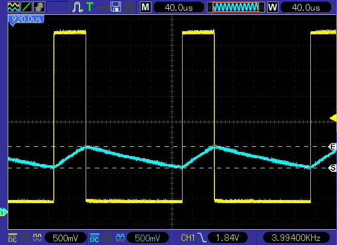
Filter A - steady state output voltage
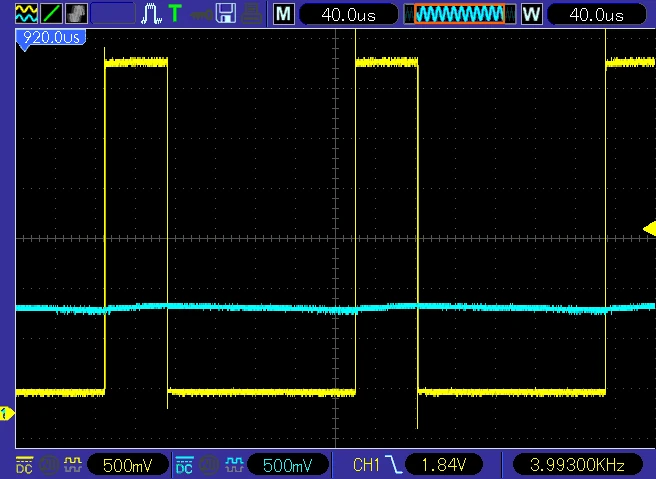
Filter B - steady state output voltage
With filter A, whose cutoff frequency is set at 1/10 of the PWM frequency, the output still shows a ripple of about 400 mV. Filter B, with its cutoff at 1/100 of the PWM frequency, brings the ripple down to roughly 40 mV, an order of magnitude smaller.
In short, a lower cutoff frequency gives you a cleaner steady state output.
Dynamic output voltage#
Now let’s examine how each filter responds when the duty cycle changes abruptly, stepping from 25% to 80%.
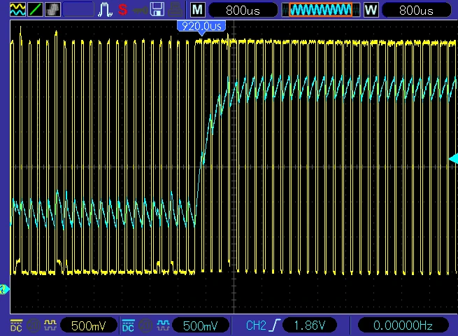
Filter A - step change output voltage
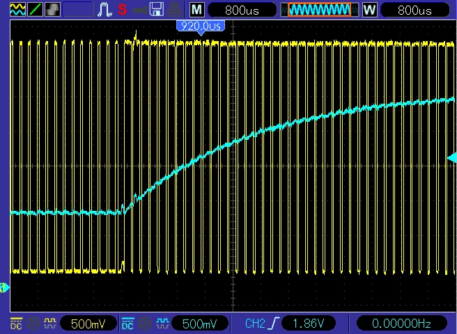
Filter B - step change output voltage
Filter A reacts quickly, and the output settles to its new value shortly after the duty cycle changes. Filter B, with its much lower cutoff frequency, takes considerably longer to reach the same steady state.
This behavior matches what we expect from a first-order RC network: after a step change, the output needs approximately 5 time constants (\(5RC\)) to settle to its final value. Since filter B has a larger \(RC\) product, its response is correspondingly slower.
In short, a lower cutoff frequency means a slower response to changes in the duty cycle.
Going further#
The simple RC filter we used in this article is a good starting point, but the tradeoff between ripple and response speed is fundamental and cannot be solved with a single resistor and capacitor. If your application demands both low ripple and fast response, you need to look beyond this first-order topology.
One option is to use higher-order filter topologies, which offer steeper attenuation and can be tailored to different needs. A good example is the Bessel filter, which provides a smooth phase response and is well suited to applications where preserving the shape of the signal matters.
Another consideration is efficiency. The RC filters we used are lossy by design: the resistor dissipates energy as heat. In low voltage, low current applications this is rarely a concern. When power efficiency matters, you can replace the resistor with an inductor and obtain a lossless filter with much stronger attenuation. This is, in essence, the principle behind the buck converter, a cornerstone of switched-mode power supply design.
Conclusion#
In this article, we explored pulse width modulation (PWM) and how to generate it using the ledc peripheral on Espressif devices. We started from the fundamentals of a PWM signal, including the duty cycle and switching frequency, and showed how the average voltage related to these parameters. We then configured the LEDC timer and channel using ESP-IDF APIs, and generated a 4 kHz PWM signal with 75% duty cycle on GPIO 25.
Finally, we examined how to convert a PWM signal into a clean DC value using an RC filter. We compared two filter designs and discussed the tradeoff between ripple attenuation and response speed. We also mentioned that more advanced topologies, such as the Bessel filter or replacing the resistor with an inductor to build a buck converter, could achieve better performance for specific applications.