
Robot soccer, briefly#
RoboCupJunior Soccer Infrared is autonomous robot soccer. Each team fields two robots, the ball emits infrared light, and once play starts there is no operator and no off-field computer: the robots find the ball, work out which way they are facing, stay inside the field and score.
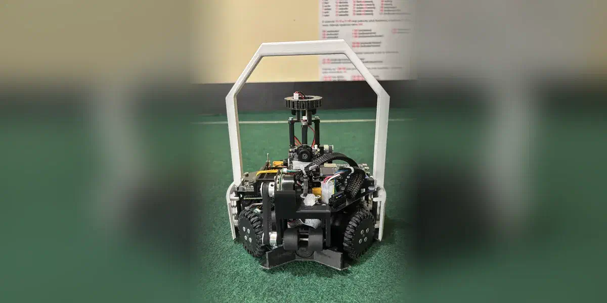
The hard limit is weight — ours came in at 1.4 kg against a 1.5 kg limit, 22 cm across — and almost everything below follows from that.
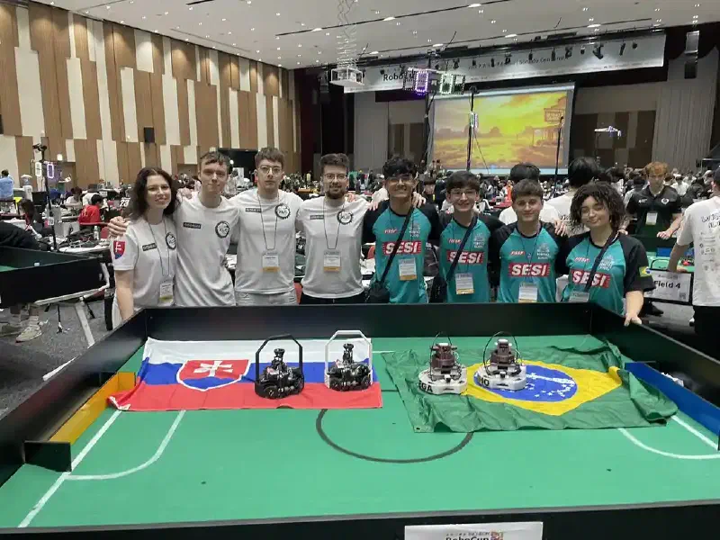
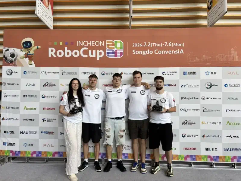
We are XLC – WYLDFYRE, four students from Slovakia: Martin Šuriak on hardware and 3D modelling, Ondrej Peter on electronics, Jakub Bohunický on both, Diana Kunová on software. We qualified 2nd at the 2026 Slovak championship; the world final ran 2–6 July 2026 in Incheon.
It started badly. In our opening game both robots stopped at the same moment — loose cables, not a crash — and by the time we found them Brazil was ten points ahead. We fixed it mid-match and still lost, 7:11. That game is a fair summary of the tournament: the engineering worked, and what beat us was a connector and an attacker that was merely good while our defender was excellent. We finished 11th of 24 with three wins, one draw and three losses.
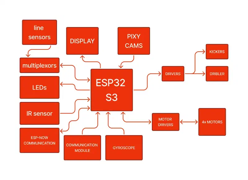
Everything below runs on an ESP32-S3-DevKitC-1, one per robot. The code is on GitHub.
The robot#
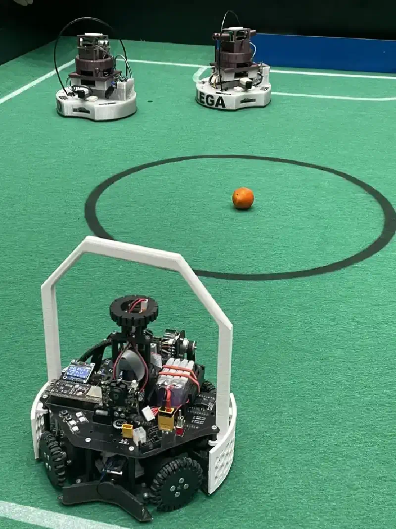
Both robots are identical, deliberately, so “attacker” and “defender” are only software states.
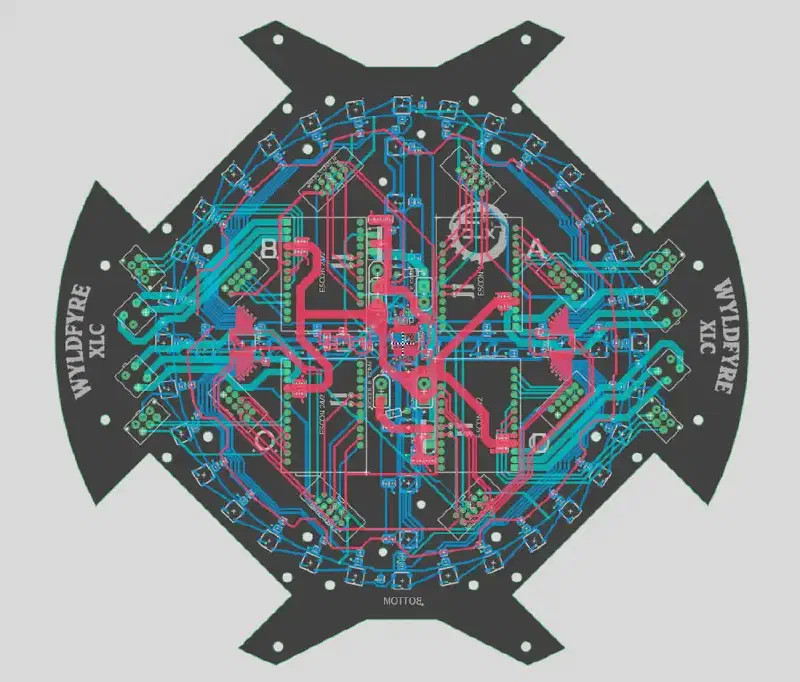
With a 1.5 kg limit, a frame that only holds things together is weight not spent on motors, so we did not build one. The robot is two custom four-layer PCBs, and those boards are the structure. Four home-made omni wheels — designed in Fusion 360, 3D printed, assembled with wire and silicone rings — each driven by a Maxon motor through a Maxon ESCON 24/2. Those are very capable pieces of hardware that have turned out to be very helpful for precise and fast movement.
The dribbler is a Maxon motor driving a rubber roller, and knowing whether it has the ball is our favourite piece of the robot. When the roller lifts to take the ball it opens a switch salvaged from a computer mouse, wired straight to a GPIO pin. It is about as simple as a sensor gets, and it never let us down. The kicker is a solenoid fed at 48 V through a PM8834 gate driver, which caused us more trouble than anything else on the robot.
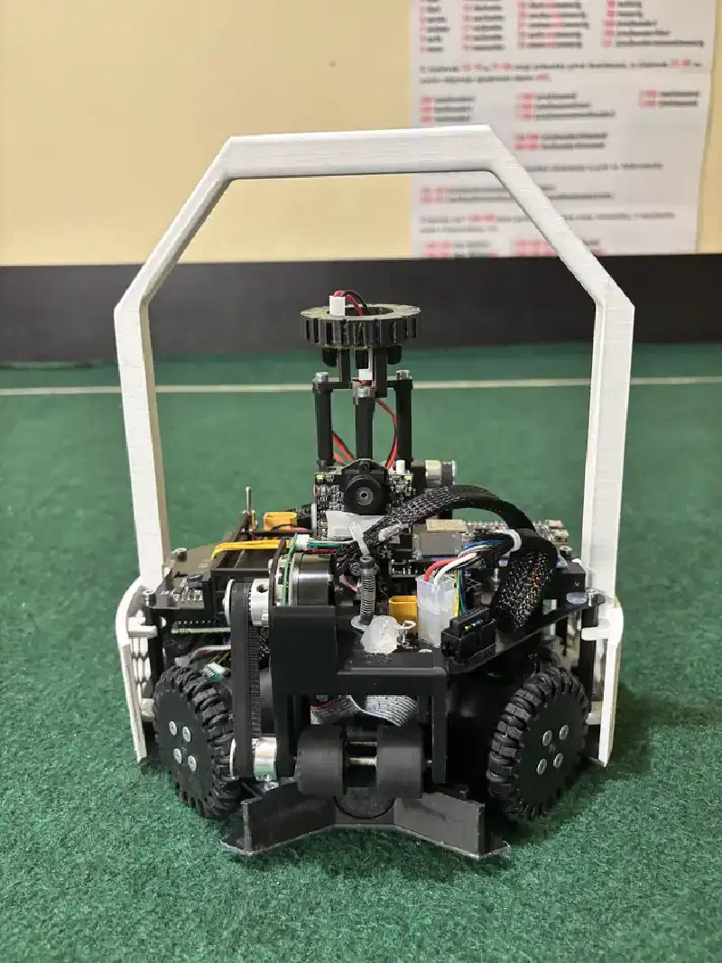
Power is a four-cell Li-HV pack, 1100 mAh, good for about 20 minutes of play. For sensing: 48 phototransistors and 48 RGB LEDs underneath, an MRMS IR Ball Finder 3, a BNO055 for heading, and two Pixy2 cameras front and rear for the goals.
Why the ESP32-S3#
We did not pick it from a comparison table. We got the choice wrong twice first.
Teensy 4.1 is fast and would have worked, but it is expensive and easy to destroy with one mishap.
Arduino Mega Pro was a really bad mistake, picked for the reason a lot of bad decisions get made: we already had them at home. Memory hurt most. It was full almost all the time, so we wrote simpler code than the robot needed — not because simple was better, but because the good version would not fit. And floating-point maths was unusable at the speeds our robot moves.
That is the whole argument. The line-angle calculation alone runs sin and cos across 32 sensors at
333 Hz, and the rest of the cycle wants atan2f and a PD loop with a real dt. An ATmega2560 is an
8-bit core at 16 MHz with no floating-point unit, so all of that is software emulation. The ESP32-S3
is a dual-core 32-bit processor at 240 MHz with hardware floating point. That is the difference
between writing the control law you want and writing the one that fits.
Performance let us stop compromising, but ESP-NOW is why we would choose the chip again — the whole two-role strategy depends on it. The peripherals covered the rest, including one we did not plan for: Bluetooth let us connect a PS5 controller, and driving the robot by hand while watching live sensor values turned out to be how we calibrated it.
Every pin on the board#
Count what this robot drives. Four motors, each needing PWM and direction, plus a shared enable. A dribbler. Two kicker channels. Four speed feedback lines. Two dribbler contacts. Two addressable LED strings. An I2C bus. Two buttons. The referee module. And a sixteen-channel address bus plus three analog returns for the line sensors.
That is thirty-three GPIOs, and the DevKitC-1 has thirty-three only if you use the pins the documentation warns you about. The table also lists GPIO43/44, which we left free for UART0, our only console.
All four strapping pins became our multiplexer address bus. GPIO0, 3, 45 and 46 are the pins the S3 samples at reset to decide how to boot. We drive them as plain outputs carrying a 4-bit address. This works because strapping pins only matter in the brief window at reset, and our multiplexer address inputs are high-impedance, so nothing pulls them during it. Across a season and a week of competition it never caused a single boot problem.
Disabling PSRAM gave us three more pins. We bought N8R8 boards, then set board_build.psram = none. We did not need the memory; we needed GPIO35, 36 and 37, which on an octal-PSRAM part are tied
to the PSRAM bank. Turn PSRAM off and you get them back.
The native USB pins became our two buttons. GPIO19 and GPIO20 are USB D− and D+, which is why we flash over the UART bridge instead.
GPIO39 to 42 are the S3’s JTAG pins and we use all four, but we never needed JTAG. We debugged through the OLED instead: it carries a menu system for picking sides and roles before a match, and it can show live values while the robot drives around untethered, which a cable-bound debugger cannot. Four addressable status LEDs do the rest, flagging at a glance whether the robot sees the ball, the line or a goal.
| Pin | Function | Note |
|---|---|---|
| 0 / 45 / 46 / 3 | Line mux address bits 0–3 | all four strapping pins |
| 4 / 5 / 6 | Line mux analog returns | ADC1_CH3–5 |
| 8 / 9 | I2C SDA / SCL | 400 kHz, five devices |
| 2 / 10 / 7 / 21 | Dribbler direction, enable; front, rear kicker | |
| 11–14, 41 / 42, 47 / 48 | Motor A–D PWM and direction | 41 / 42 are JTAG MTDI / MTMS |
| 15–18 / 38 | Motor speed feedback / shared enable | |
| 19 / 20 | Button − / + | USB D− / D+ |
| 35 / 36 / 37 | Referee module, two WS2812B strings | PSRAM bank |
| 39 / 40 | Dribbler contacts, rear / front | JTAG MTCK / MTDO |
| 43 / 44 | free | UART0, our only console |
48 analog sensors, three multiplexers#
The robot has to know where the white boundary line is, in every direction, all the time. The ESP32-S3 has ten usable ADC1 channels and we needed 48 readings, so the sensing system hangs off three CD74HC4067 sixteen-channel multiplexers sharing one 4-bit address bus.
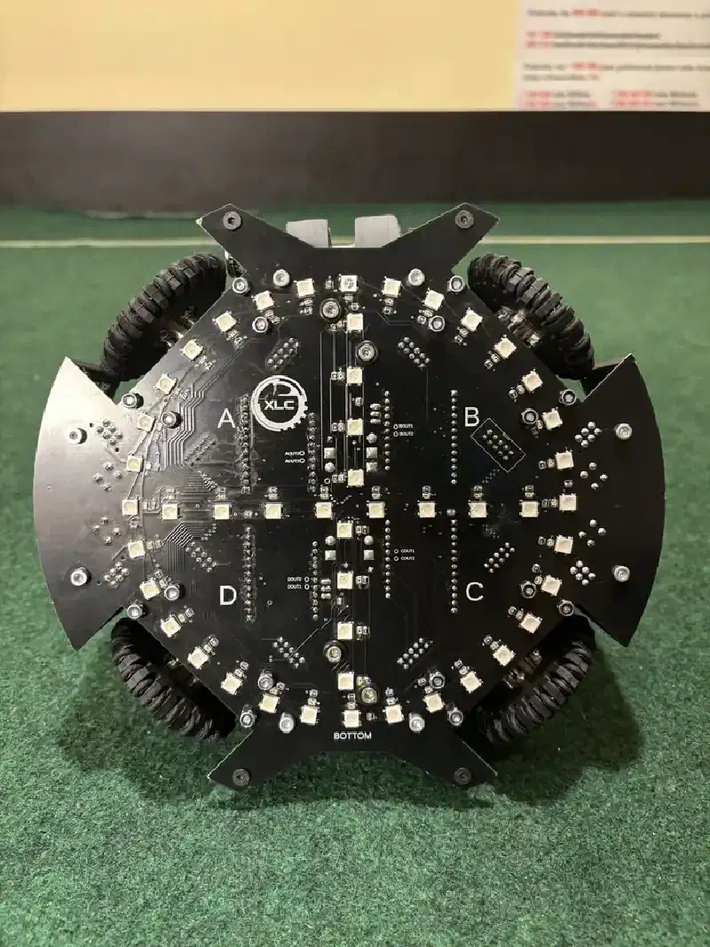
Each phototransistor sits next to an addressable RGB LED. The LED lights the floor, the phototransistor measures what comes back: green carpet reflects little, a white line reflects a lot.
Being able to choose the colour matters here. Red gives the sharpest contrast between white line and green carpet, but the rules do not allow it, so we settled on violet and pink, which came a close second. Even so, the separation was beautifully clean — line and carpet readings sit far enough apart that we never needed per-sensor calibration. One threshold, 250 counts out of 4095, was enough for all 48 channels.
Reading all 48 is one loop of sixteen steps. Set the address once and all three multiplexers move together, so each iteration yields three samples:
static void _input_scanMux() {
    for (uint8_t addr = 0; addr < 16; addr++) {
        _input_setMuxAddr(addr);                                    // 4 GPIOs, 4-bit address
        line_ADC_ring[addr]      = analogReadFast(HW::LineCfg::Line_A_Read_ADC_CH);
        line_ADC_ring[addr + 16] = analogReadFast(HW::LineCfg::Line_B_Read_ADC_CH);
        line_ADC_depth[addr]     = analogReadFast(HW::LineCfg::Line_X_Read_ADC_CH);
    }
}
That runs at 333 Hz: about 16,000 ADC samples per second, alongside everything else.
The 48 are really two arrays. Thirty-two form a ring around the perimeter, one every 11.25°,
answering which direction is the line: each triggered sensor becomes a unit vector at its own angle,
summed, and atan2 gives the result. Sixteen more form four arms of four, pointing outward,
answering how far onto the line are we — each position along an arm is worth a fixed fraction of the
robot being across it.
Comparing the front arm against the rear gives a signed number we call depth_Y, and that is the
reason our defender worked. Most robots treat the line as a wall to bounce off. Because we could
measure how much of the robot was across it, we could use it as a position reference instead —
and a painted line does not drift, does not need recalibrating, and does not care about the lighting.
The main loop#
The firmware runs out of loop(): read the world, decide what state the robot is in, act on it,
write the outputs, same order every cycle. We did not create any FreeRTOS tasks of our own.
Reading a gyro is cheap; reading a camera over I2C is not. So each input gets its own interval checked
against millis(): 1 kHz for heading, 333 Hz for the line array, 200 Hz for the ball, 5 Hz for
ESP-NOW. The cameras get the most interesting treatment — 10 Hz when we are holding the ball or
defending, 1 Hz otherwise, because a Pixy read is the most expensive thing on our I2C bus.
The second core is not idle, though. The Arduino core pins loop() to one core and the Wi-Fi stack
carrying ESP-NOW runs on the other, so the radio work happens in parallel with the control loop.
Motion without trigonometry#
Driving a four-wheel omnidirectional robot in a given direction means giving each wheel a different share of the effort. The textbook approach solves that trigonometry at runtime; we solve it once, offline, for every whole degree, and ship a 361-row table of wheel weights for 5,776 bytes of flash.
The more useful idea sits on top of the table. Nothing in this firmware tells the motors what to do. Behaviours add to a shared vector, and whatever has accumulated by the end of the cycle is what the robot does:
void addMotion(float angle, float weight) {
    int16_t a = _motion_wrap360((int16_t)lround(angle));
    OUT::motorAcc.mainOut[0] += motionAngles[a][0] * weight * ST::soccer.baseSpeed;
    OUT::motorAcc.mainOut[1] += motionAngles[a][1] * weight * ST::soccer.baseSpeed;
    OUT::motorAcc.mainOut[2] += motionAngles[a][2] * weight * ST::soccer.baseSpeed;
    OUT::motorAcc.mainOut[3] += motionAngles[a][3] * weight * ST::soccer.baseSpeed;
}
Behaviours blend instead of fighting. The attacker adds a vector toward the ball; if the line sensors trigger, line avoidance adds its own vector away from the boundary, weighted by how far across the line the robot already is. We never wrote arbitration logic — the robot leans away from the line more strongly the closer it gets, because that is what the arithmetic does.
The accumulator is wiped after it reaches the motors, a quiet safety property: a behaviour that stops asking for motion stops the robot. Each motion function also has a field-relative twin that subtracts the gyro heading first, so holding a heading and moving sideways become independent decisions — which is what makes the next section possible.
One more detail, because it is the kind that costs an afternoon. The ESCON drivers read duty cycle as a setpoint and treat the extremes as no valid signal, so we remap every command into a 9–89% window. A naive write of zero does not mean “stop”, it means “the controller has lost its command” — which we use deliberately, writing a true zero when the motors are disabled so the drivers shut down on their own.
The defender everyone asked about#
Over the week in Incheon, several teams came over to ask the same question: how did we build a defender that good? It was the part of our robot that genuinely competed with the top teams.
A defender needs to know where it is — precisely, for a whole match, while being shoved. The usual options all decay. Dead reckoning on omni wheels drifts within seconds, because omni wheels slip by design. An IMU gives you heading, not position. And treating the line as a wall tells the robot only that it has gone too far, never where it is.
Ours uses two absolute references instead. The rear camera gives it the goal: a Pixy2 facing
backwards reports the goal’s angle and apparent size, and neither drifts, because both measure
something bolted to the field. The line array gives it depth, straight from depth_Y. Two
references, both absolute, both measured fresh every cycle.
It never turns around. The first version rotated to face the ball, like most defenders do. We abandoned it: it was less stable, and you cannot hold a ball in a dribbler while rotating back and moving fast at an angle. So our defender holds one heading all match and only strafes.
The core is four lines, and the important one computes the sideways component as
sin(ball angle) × proximity, clamped to ±0.25. The sine does the real work: it is the ball’s
projection onto the goal line. A ball straight ahead gives zero, so the robot holds still; a ball at
90° gives one, so it moves at full authority; a ball behind at 170° gives a small value, because that
is not a shot yet. Exactly what a goalkeeper should do, out of one trig call. Proximity adds the rest
— do not commit to a distant ball — and a proportional term on depth_Y holds the robot’s centre on
the goal line.
It refuses to start until it knows where it is. A defender that begins in the wrong place is worse than useless, so ours hunts for the goal with the rear camera until two conditions hold together: the camera has seen our goal within 500 ms, and the line sensors are on the line.
If it crosses the line on one side, the defender latches that side and re-clamps its strafe so it can only push back toward the centre. The result is what we are proudest of: it covered the full width of the goal and nothing beyond it, and never needed recalibrating.
Two robots, one strategy#
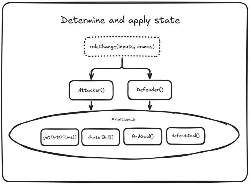
Because the hardware is identical, roles are values in a struct — the roleChange box at the top of
the diagram in the previous section. Swapping them at runtime costs nothing, because both roles
already sit on the same shared primitives.
ESP-NOW makes swapping practical. A competition hall is a hostile place for radio—dozens of teams, even more laptops, and phones. ESP-NOW has none of that: set a channel, register a peer MAC, and send.
Both robots run one firmware image, and a menu setting decides which peer MAC to talk to. What they send is small and infrequent — five hertz:
struct __attribute__((packed)) Soccer_MSG {
    uint16_t seq;                  // packet sequence number
    int8_t   mode;                 // in the menus, or playing soccer
    int8_t   role;                 // attacker or defender
    uint8_t  drbF;                 // is the dribbler holding the ball
    int8_t   code;                 // command: swap roles
    uint8_t  referee;              // referee module state
    uint16_t ball_angle_ToNField;  // where I see the ball, in field coordinates
    uint16_t ball_distRaw;         // how far away the ball is
    uint8_t  line_seen;            // am I on the boundary line
    uint16_t gyro_offset_ToNField; // my heading
    uint8_t  goalEnemy_seen;       // is the enemy goal in view
};
This is deliberately not a control channel. Neither robot tells the other where to drive; they exchange situational awareness plus one command code for swapping roles. Everything time-critical stays local, which is why 5 Hz is plenty and a dropped packet is never a disaster.
A swap is triggered by holding both buttons, or by the ball: a defender that wins possession promotes itself to attacker, then demotes itself two seconds after losing it. A minimum dwell time guards that, because the first version oscillated, and two robots flipping roles several times a second is funny to watch exactly once.
It is the feature that kept us in games. When a robot goes down, and in our first match both did, the survivor is not stuck playing half a strategy.
What broke#
Cables. Both robots stopped at the same moment in our first match because connectors had worked loose. A robot that accelerates hard in four directions, gets hit by other robots and fires a solenoid is a machine designed to shake its own wiring apart. The fix was glue.
The gate driver we kept destroying. This is the one that cost us real hardware. The kicker solenoid needs a large current in a short pulse, so we wanted as much gate drive as we could get. The PM8834 is a dual driver, and its datasheet says the two outputs may be merged to drive a single load. So we merged them.
It did not work. We blew gate drivers repeatedly, and several times the failure took the ESP32-S3 with it.
The attacker. We built a defender that competed with the best in the world and an attacker that did not. We finished 3-1-3, and the pattern is not subtle: we could stop other teams scoring and could not reliably score ourselves. Ball chasing was still being tuned in Incheon, while everything we were proud of belonged to the defender. All that rigour went into the half that prevents goals.
Everything else transferred almost perfectly from Slovakia to Korea, because a RoboCup field has fixed dimensions — so our time on site went entirely to the problem we had not solved before we arrived. Solve the hard behaviour at home; the venue will not give you time to think.
What we would do differently#
A better attacker. This is the whole list, really. The defender proved the approach works — absolute references, measured rather than estimated position, a control law simple enough to reason about — and we never gave the attacker that treatment.
Our own ball fusion. We trust the commercial MRMS module’s angle directly, and rate it mediocre — but its filtering beats what we managed ourselves. Our own version already exists in the repository, compiled out behind a flag, and it is the more sophisticated pipeline. It is not yet the better one, because the module filters noise we have not characterised. Next year’s job is not writing the fusion, it is measuring the sensor well enough to beat the vendor at it.
Two dribblers and two kickers. We planned this and ran out of time, and what is easy to miss is
how close we got: the boards carry front and rear connectors for both, and the firmware has
kickFront() and kickRear(). What it lacks is one uncommented line reading the rear dribbler
contact. The reason follows from the defender — it never rotates, except when it wins possession and
has to turn to kick, the one moment it does the thing we designed it not to do.
What we are taking away#
Eleventh of twenty-four is not a podium and we will not dress it up as one. It is a fair description of where we are: a team that can build hardware and control systems at the level of the best in the world, and has not yet built a complete robot at that level.
The ESP32-S3 never failed to do its job — not at 1 kHz on the heading loop, not with 16,000 ADC samples a second, not with ESP-NOW running on the other core. The boards we destroyed, we destroyed ourselves, through a gate driver wired the way a datasheet said we could.
Three things worth stealing:
- Let behaviours blend instead of arbitrating. Summing weighted vectors into an accumulator gave us line avoidance for free, with no priority logic to get wrong.
- Know which pins you are spending. Strapping pins, the PSRAM bank, native USB and JTAG can all be used as GPIOs, but decide that up front. We ended up using them only because we ran out of pins.
- A datasheet’s permission is not a test result. Merging two driver outputs was allowed on paper and destroyed hardware on our board.
Our thanks to Espressif for the development platforms at the centre of both robots. Firmware, schematics, board layouts and the competition poster are all in the repository: