“I would like to start a new product design with my favorite chip but it’s out of stock! Oh, no! I’ll have to design a new layout and develop new drivers for it!” Every designer knows that feeling very well these days…
The good news is you don’t have to worry about a such thing anymore, at least in terms of ESP-IDF Ethernet PHY driver support. In this article, I’ll demonstrate to you how simple it is to create a new Ethernet PHY driver.
First of all, you need to find a replacement for your current PHY chip. I have a friend working for a semiconductors distribution company so I just picked up my phone and asked him for some advice. He recommended ADIN1200. It’s a robust industrial-grade chip with a wide set of features. It’s an ideal candidate for our demonstration purposes, since an evaluation board exists, the chip is from a vendor which is currently not supported by ESP-IDF (i.e. we limit the possibility of vendor locking for our customers) and the chip is IEEE 802.3 compliant. The last fact will help us the most to reduce the effort needed for a new driver creation since a management interface between EMAC and PHY is standardized and the ESP-IDFv5.0 takes advantage of it. The ESP-IDF Ethernet driver basically consists of three layers:
- The Ethernet objects itself which is the public API and which wraps MAC and PHY layers into one functional unit.
- The MAC layer controls the behavior of the Media Access Controller and provides a data interface to the driver application.
- The PHY layer controls physical layer properties and gathers the status of the link.
The “22.2.4 Management Functions” section of the IEEE 802.3 standard defines provisions of the so-called “MII Management Interface” for the purposes of controlling the PHY and gathering status from the PHY by MAC. A set of management registers is defined and this basic management functionality is addressed by the ESP-IDF Ethernet driver as a set of common functions. Therefore, you as an author of the new PHY driver can focus only on chip-specific features like:
- Link status indication which is almost always chip-specific.
- Chip initialization. This part is not strictly required, since it’s most common. It’s good to be added to ensure that the expected chip is used.
- Chip-specific features configuration (such as Wake on LAN, Energy Efficient Ethernet, various diagnostics capabilities, etc).
Let’s demonstrate the creation of the driver step by step#
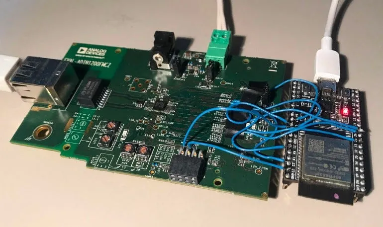
In terms of hardware, it is easiest to start with the EVAL-ADIN1200 evaluation board. This evaluation board only requires a few modifications to be connected to ESP32 via RMII. (You can, of course, start with a new PCB design if you find it more appropriate.)
Steps to prepare the hardware:
Study materials at the ADIN1200 product page and get familiar with the chip and the evaluation board.
Once you are familiar with the evaluation board, the following modifications are required:
- ADIN1200 requires an external 50 MHz RMII REF_CLK, therefore de-solder the Y1 oscillator and its associated coupling capacitors.
- Solder R120 with 0R resistor
- Solder 10K pull-ups at RX_CTL(High) and RX_CLK (High) to configure ADIN1200 into RMII mode.
- For additional configuration options, consult “*Table 5. EVAL-ADIN1200FMCZ Configuration Setting” *in the EVAL-ADIN1200FMCZ User Guide.
- Connect ADIN1200 RMII interface to ESP32. I soldered wires to the exposed 0R resistors as shown in the below Table. Try to keep wires as short as possible and all with the same length.
Note that RMII REF_CLK needs to be generated externally to ADIN1200 either by an external 50 MHz oscillator or by ESP32. It is simpler to use ESP32 for our demonstration purposes so I used that solution, but keep in mind that the ESP32 WROOM module is required.
╔════════════════════╦═════════════════╦═════════════╗
║ RMII Interface Pin ║  EVAL-ADIN1200  ║ ESP32 WROOM ║
╠════════════════════╬═════════════════╬═════════════╣
║ TX_EN              ║ R80             ║ GPIO21      ║
║ TXD[0]             ║ R90             ║ GPIO19      ║
║ TXD[1]             ║ R88             ║ GPIO22      ║
║ RXD[0]             ║ R99             ║ GPIO25      ║
║ RXD[1]             ║ R86             ║ GPIO26      ║
║ CRS_DV             ║ R81             ║ GPIO27      ║
║ RESET              ║ R213            ║ GPIO5       ║
║ REF_CLK            ║ C92             ║ GPIO17      ║
║ MDIO               ║ MDIO Test Point ║ GPIO18      ║
║ MDC                ║ MDC Test Point  ║ GPIO23      ║
╚════════════════════╩═════════════════╩═════════════╝
The result of EVAL-ADIN1200 modification is shown in the figure below.
From software point of view, it’s even simpler.
Steps to create the new Ethernet PHY driver:
Create a copy of esp_eth_phy_ip101.c or any other IEEE 802.3 compatible PHY chip source file from the ESP-IDF /components/esp_eth/src/ folder to a new folder.
Rename all occurrences of “ip101” to “adin1200”.
Update the “Vendor Specific Registers” code section with ADIN1200 registers you are planning to use. I’ve only updated the “PHY Status 1 Register” since I’m not planning to use any of the advanced features yet.
/***************Vendor Specific Register***************/
/**
 * @brief PHY Status 1 Register
 *
 */
typedef union {
    struct {
        uint32_t lp_apause_adv : 1; /* The link partner has advertised asymmetric pause */
        uint32_t lp_pause_adv : 1; /* The link partner has advertised pause */
        uint32_t autoneg_sup : 1; /* Local and remote PHYs support autonegotiation */
        uint32_t col_stat : 1; /* Indicates that collision is asserted */
        uint32_t rx_dv_stat : 1; /* Indication that receive data valid (RX_DV) is asserted. */
        uint32_t tx_en_stat : 1; /* Indication that transmit enable (TX_EN) is asserted */
        uint32_t link_stat : 1; /* Link status */
        uint32_t hcd_tech : 3; /* Indication of the resolved technology after the link is established */
        uint32_t b_10_pol_inv : 1; /*  polarity of the 10BASE-T signal inversion */
        uint32_t pair_01_swap : 1; /* Pair 0 and Pair 1 swap */
        uint32_t autoneg_stat : 1; /* Autonegotiation Status Bit */
        uint32_t par_det_flt_stat: 1; /* Parallel Detection Fault Status Bit */
        uint32_t reserverd : 1; /* Reserved */
        uint32_t phy_in_stndby : 1; /* PHY is in standby state and does not attempt to bring up links */
    };
    uint32_t val;
} ps1r_reg_t;
#define ETH_PHY_PS1R_REG_ADDR (0x1A)
- Update expected oui and model in adin1200_init() function based on the content of “PHY Identifier 1/2 Register”* *defined in datasheet.
/* Check PHY ID */
uint32_t oui;
uint8_t model;
ESP_GOTO_ON_ERROR(esp_eth_phy_802_3_read_oui(phy_802_3, &oui), err, TAG, "read OUI failed");
ESP_GOTO_ON_ERROR(esp_eth_phy_802_3_read_manufac_info(phy_802_3, &model, NULL), err, TAG, "read manufacturer's info failed");
ESP_GOTO_ON_FALSE(oui == 0xa0ef && model == 0x02, ESP_FAIL, err, TAG, "wrong chip ID (read oui=0x%" PRIx32 ", model=0x%" PRIx8 ")", oui, model);
- Modify the update_link_duplex_speed() function to read the actual negotiation result. This information is not standardized under IEEE 802.3 hence all PHY chips differ at this point. ADIN1200 indicates this data in the “PHY Status 1 Register”.
...
    ESP_GOTO_ON_ERROR(eth->phy_reg_read(eth, addr, ETH_PHY_ANLPAR_REG_ADDR, &(anlpar.val)), err, TAG, "read ANLPAR failed");
    ESP_GOTO_ON_ERROR(eth->phy_reg_read(eth, addr, ETH_PHY_BMSR_REG_ADDR, &(bmsr.val)), err, TAG, "read BMSR failed");
    eth_link_t link = bmsr.link_status ? ETH_LINK_UP : ETH_LINK_DOWN;
    /* check if link status changed */
    if (adin1200->phy_802_3.link_status != link) {
        /* when link up, read negotiation result */
        if (link == ETH_LINK_UP) {
            ps1r_reg_t ps1r;
            ESP_GOTO_ON_ERROR(eth->phy_reg_read(eth, addr, ETH_PHY_PS1R_REG_ADDR, &(ps1r.val)), err, TAG, "read PS1R failed");
            switch (ps1r.hcd_tech) {
            case 0: //10Base-T half-duplex
                speed = ETH_SPEED_10M;
                duplex = ETH_DUPLEX_HALF;
                break;
            case 1: //10Base-T full-duplex
                speed = ETH_SPEED_10M;
                duplex = ETH_DUPLEX_FULL;
                break;
            case 2: //100Base-TX half-duplex
                speed = ETH_SPEED_100M;
                duplex = ETH_DUPLEX_HALF;
                break;
            case 3: //100Base-TX full-duplex
                speed = ETH_SPEED_100M;
                duplex = ETH_DUPLEX_FULL;
                break;
            default:
                break;
            }
...
- Create a new header file with esp_eth_phy_new_adin1200() function.
… and the new PHY driver is done and ready to be used!
Now, we just create MAC and PHY objects as we are used to and initialize the ESP-IDF Ethernet driver in our application.
#include "esp_eth_phy_adin1200.h"
// Init common MAC and PHY configs to default
eth_mac_config_t mac_config = ETH_MAC_DEFAULT_CONFIG();
eth_phy_config_t phy_config = ETH_PHY_DEFAULT_CONFIG();
// Update PHY config based on board specific configuration
phy_config.phy_addr = CONFIG_EXAMPLE_ETH_PHY_ADDR;
phy_config.reset_gpio_num = CONFIG_EXAMPLE_ETH_PHY_RST_GPIO;
// Init vendor specific MAC config to default
eth_esp32_emac_config_t esp32_emac_config = ETH_ESP32_EMAC_DEFAULT_CONFIG();
// Update vendor specific MAC config based on board configuration
esp32_emac_config.smi_mdc_gpio_num = CONFIG_EXAMPLE_ETH_MDC_GPIO;
esp32_emac_config.smi_mdio_gpio_num = CONFIG_EXAMPLE_ETH_MDIO_GPIO;
// Create new ESP32 Ethernet MAC instance
esp_eth_mac_t *mac = esp_eth_mac_new_esp32(&esp32_emac_config, &mac_config);
// Create new PHY instance
esp_eth_phy_t *phy = esp_eth_phy_new_adin1200(&phy_config);
// Init Ethernet driver to default and install it
esp_eth_handle_t eth_handle = NULL;
esp_eth_config_t config = ETH_DEFAULT_CONFIG(mac, phy);
ESP_GOTO_ON_FALSE(esp_eth_driver_install(&config, ð_handle) == ESP_OK, NULL,
err, TAG, "Ethernet driver install failed");
The full version of the ADIN1200 Ethernet PHY driver is available at ESP-IDF additional Ethernet drivers repository or via IDF Component Manager.