
Internal memory of the MCU is probably the most precious resource as it occupies maximum area in the chip. The newer application use-cases have ever increasing memory requirement. For making the most of the hardware, understanding of the memory architecture and optimising of the memory for application’s use-case becomes important. Especially with the ESP32 SoC architecture that includes communication subsystems (Wi-Fi and BT/BLE) that requires certain memory to operate, it becomes necessary for the application to understand the requirements and tune their memory.
We often get questions about available memory headroom for the application; and there is no easy answer to that question unless we go into the details of the use-case. But when developers understand the details about memory layout, system requirements and the common methods to optimise, we have seen that ESP32 can accommodate quite a variety of interesting application use-cases.
This blog is intended to provide an overview of ESP32 SoC’s memory layout for application developers, explain different memory regions and their characteristics and discusses the memory allocation for a typical ESP32 firmware.
Please note that all the specific details mentioned here are with respect to ESP-IDF release version 4.0 which is the latest stable release at the time of writing of this blog.
Internal RAM Layout#
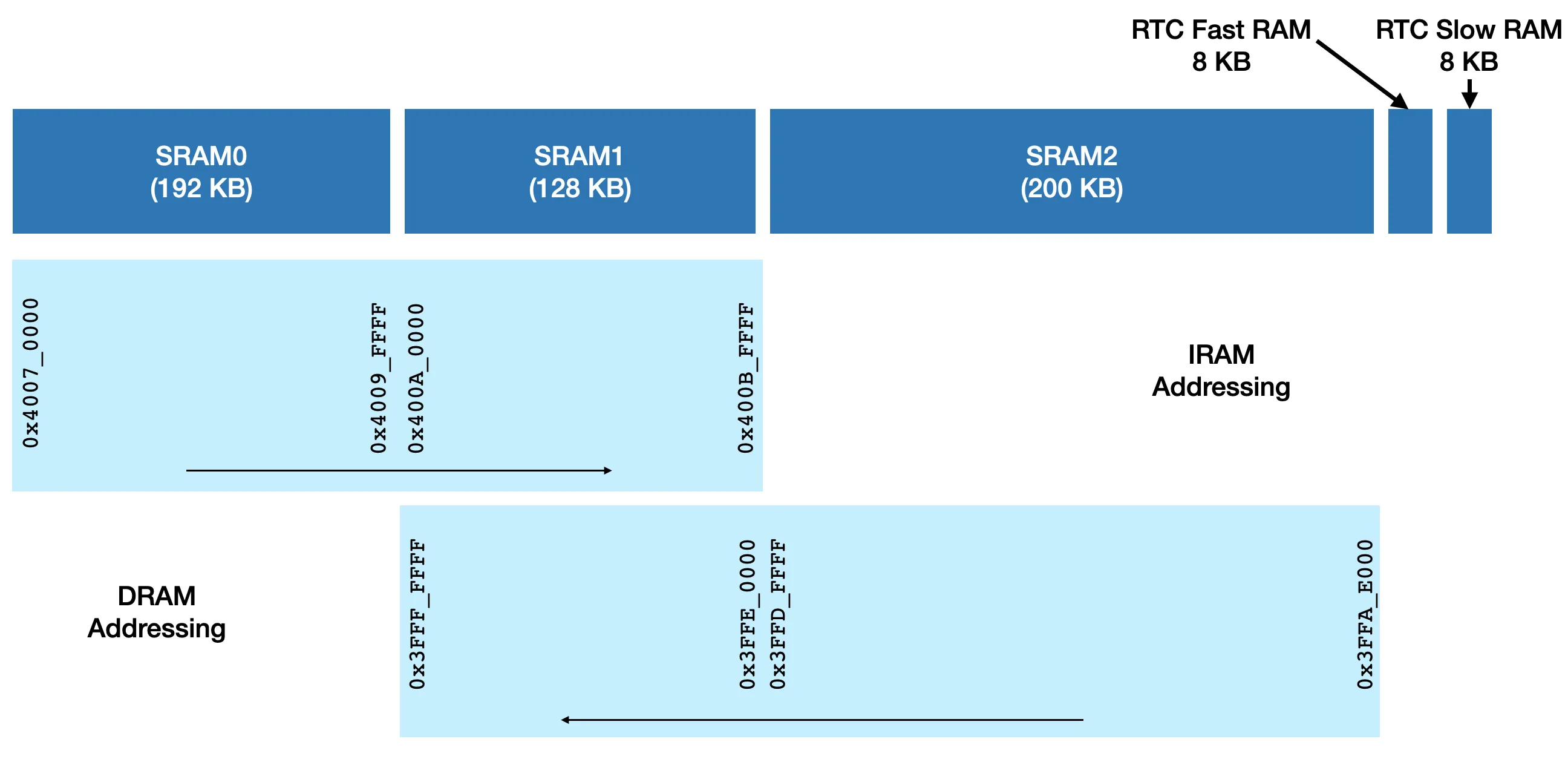
The above diagram shows the ESP32 internal memory (SRAM) layout. The SRAM is divided into 3 memory blocks SRAM0, SRAM1 and SRAM2 (and two small blocks of RTC fast and slow memory which we’ll consider separately later).
The SRAM is used in two ways — one for instruction memory — IRAM(used for code execution — text data) and data memory — DRAM (used for BSS, data, heap). SRAM0 and SRAM1 can be used as a contiguous IRAM whereas SRAM1 and SRAM2 can be used as a contiguous DRAM address space.
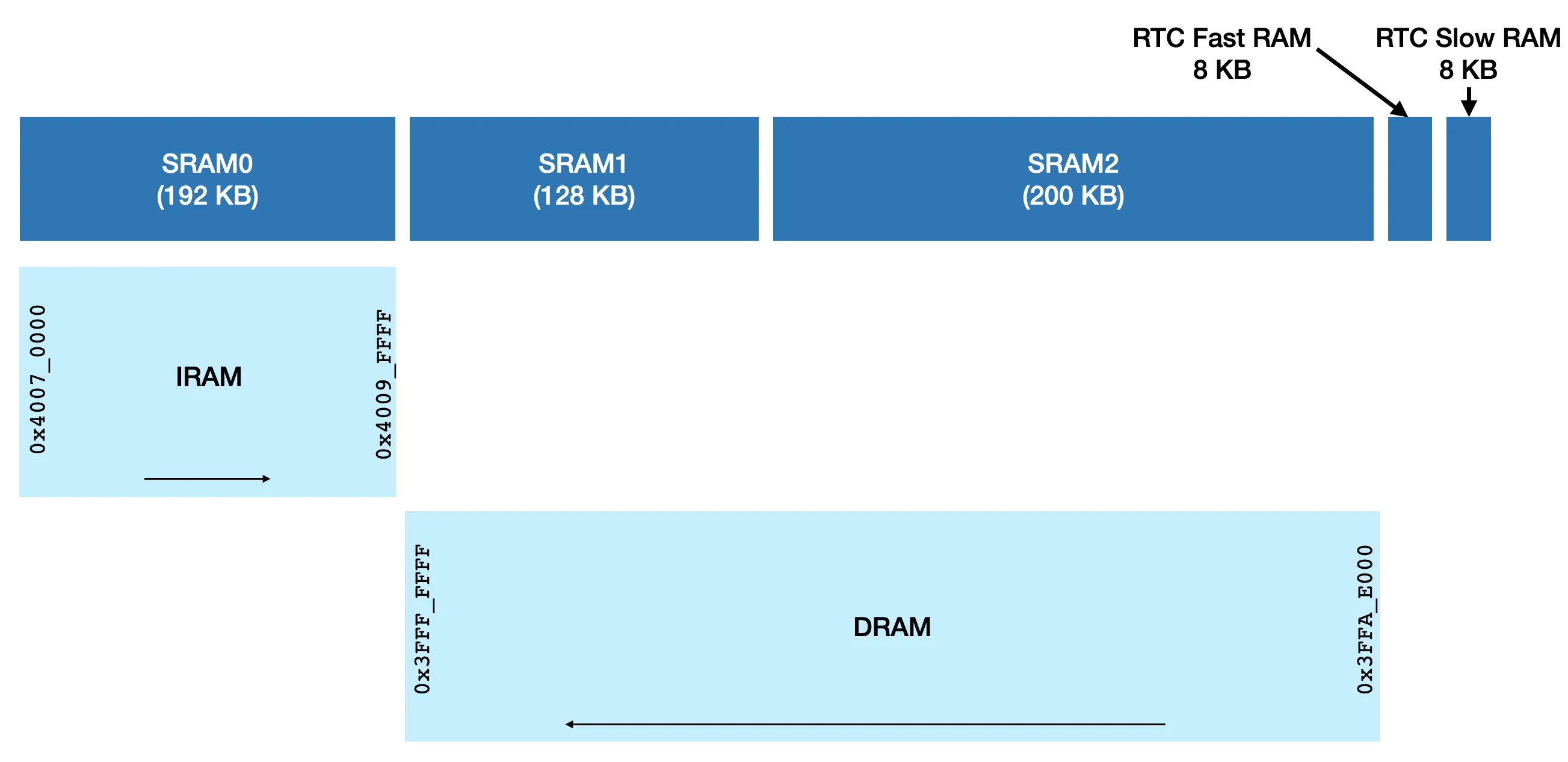
While SRAM1 can be used as a IRAM and DRAM both, for practical purposes, ESP-IDF uses SRAM1 as DRAM, as it’s generally the data memory that applications fall short of. The above diagram shows the memory map for programmers to consider for their application development where they get 192KB IRAM and 328KB DRAM. While it does not matter much for the application as there is no overlap, please note that the direction of the address range is opposite for IRAM and DRAM address spaces.
IRAM Organisation#
Lets now zoom into the IRAM section.
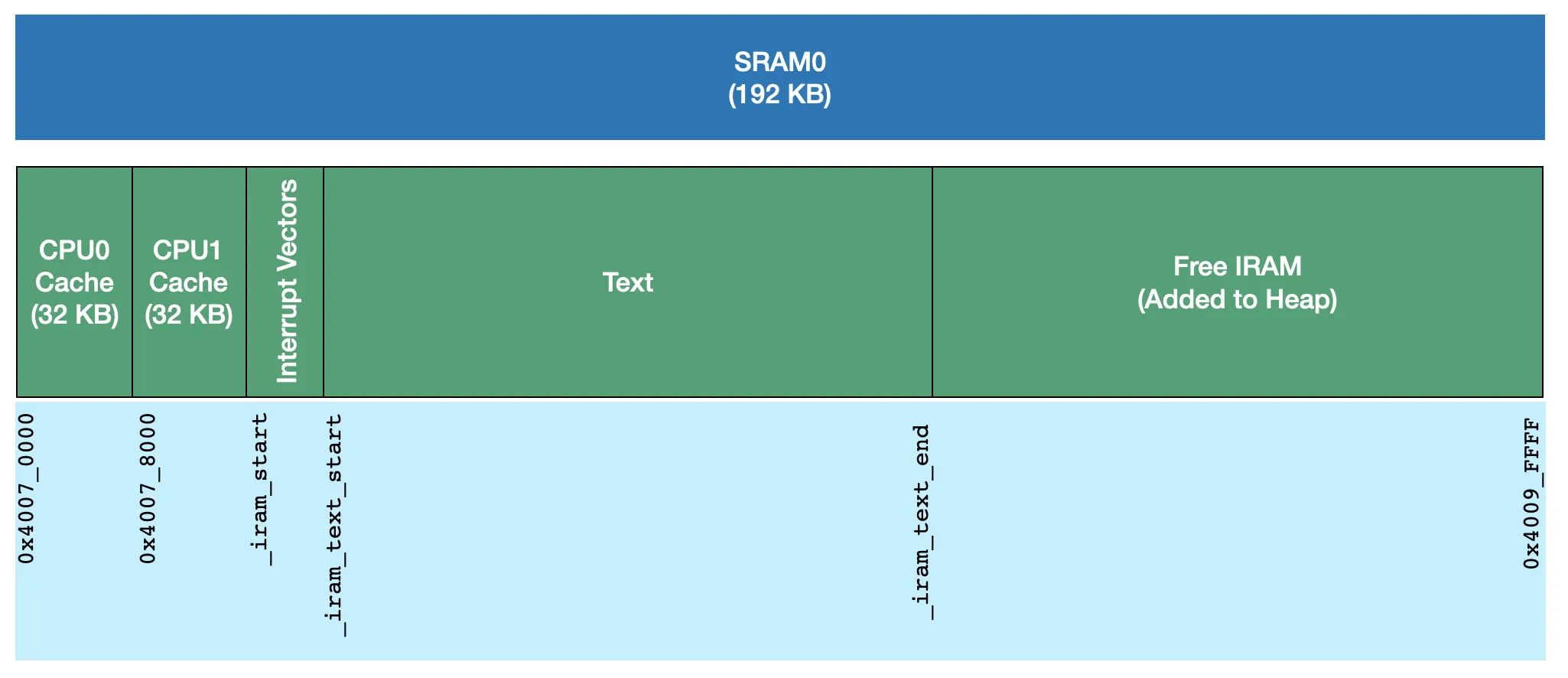
The 192 KB of available IRAM in ESP32 is used for code execution, as well as part of it is used as a cache memory for flash (and PSRAM) access.
- First 32KB IRAM is used as a CPU0 cache and next 32KB is used as CPU1 cache memory. This is statically configured in the hardware and can’t be changed.
- After the first 64KB, the linker script starts placing the text region in IRAM. It first places all the interrupt vectors and then all the text in the compiled application that is marked to be placed in IRAM. While in common case, majority of the application is executed out of the flash (XiP), there are some portions of the applications which are time critical, or that operate on flash itself. They need to be placed in IRAM and that is achieved using a special attribute to these functions or files and linker script doing a job of placing them in IRAM. The symbols _iram_text_start and _iram_text_end are placed by the linker script at the two boundaries of this text section.
- The IRAM after the text section remains unused and is added to the heap.
_iram_text_start and _iram_text_end symbols are placed by the linker script at the two boundaries of this text section. The IRAM after the text section remains unused and is added to the heap.
Also, when the application is configured in a single-core mode, the CPU1 is not functional and CPU1 cache is unused. In that case, CPU1 cache memory (0x40078000–0x4007FFFF ) is added to the heap.
The unused IRAM, that is placed in the heap, can be accessed through dynamic allocations.
It can be used to place any code in IRAM if the application has such a requirement. However this is quite uncommon.
The IRAM can also be used for data, but with two important limitations.
If the application has such data that can obey these two rules of accesses, it can make use of IRAM memory for that data.
There is also a way to access IRAM without this limitations; but as a slower memory. This is discussed in a later section.
DRAM Organisation#
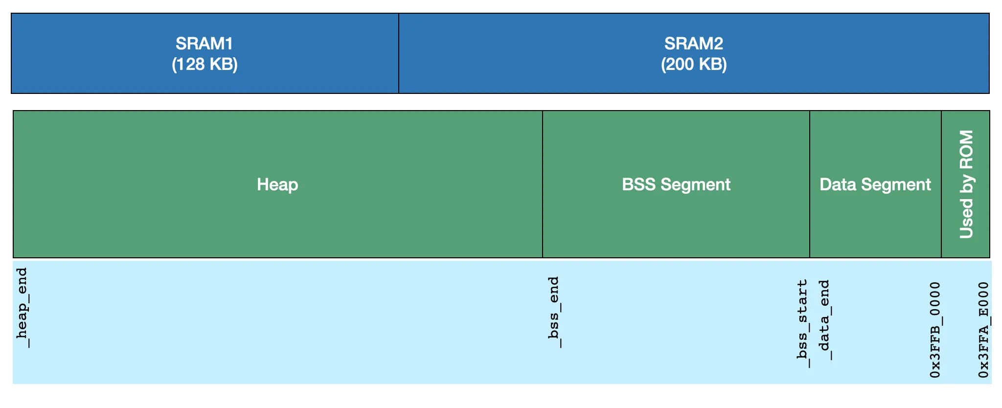
The above diagram shows a typical (simplified) DRAM layout for an application. As the DRAM addresses start at the end of SRAM2, increasing in backward direction, the link time segments allocation happens starting at the end of SRAM2.
- The first 8KB (0x3FFA_E000–0x3FFA_FFFF) are used as a data memory for some of the ROM functions.
- The linker then places initialised data segment after this first 8KB memory.
- Zero initialised BSS segment comes next.
- The memory remaining after allocating data and BSS segments, is configured to be used as a heap. This is where typical dynamic memory allocations go.
Please note that the size of data and BSS segments depend on the application. So each application, based on the components that it uses and APIs it calls has a different available heap size to begin with.
There are two regions within the heap (0x3FFE_0000–0x3FFE_0440 — 1088 bytes) and (0x3FFE_3F20–0x3FFE_4350–1072 bytes) that are used by ROM code for its data. These regions are marked reserved and the heap allocator does not allocate memory from these regions.
DRAM Organisation with BT Enabled#
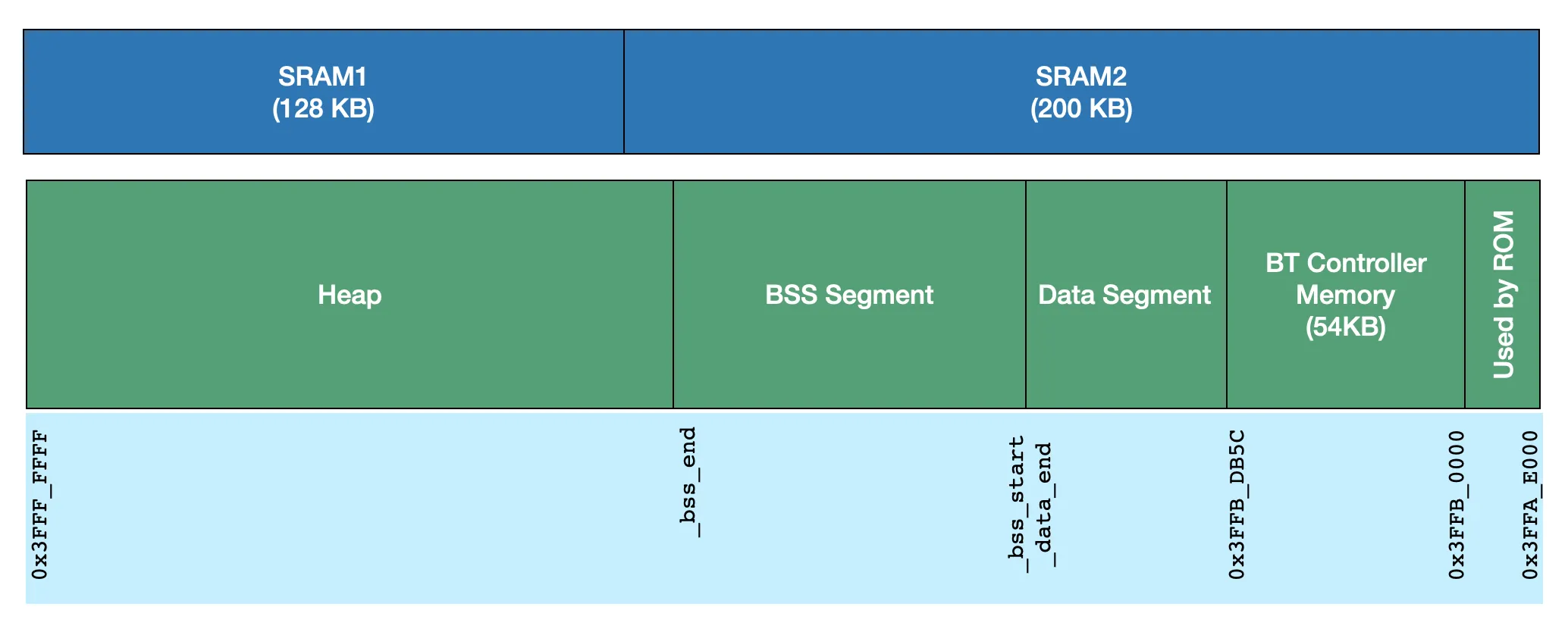
When BT functionality is enabled, the BT controller (software and hardware) needs to use a dedicated data memory. This memory is used as data/BSS for the controller as well as for transfer memory for BT packets between the software and hardware. So the linker script reserves 54KB of memory in addition to the default DRAM allocations between 0x3FFB_0000–0x3FFB_DB5C. The application’s data and BSS segment allocations continues after this region.
When only BLE functionality is used by the application, a part of the BT controller memory can be relinquished back to the heap. The amount of memory that is released and added to the heap is ~19KB.
DRAM Organisation with Trace Memory#
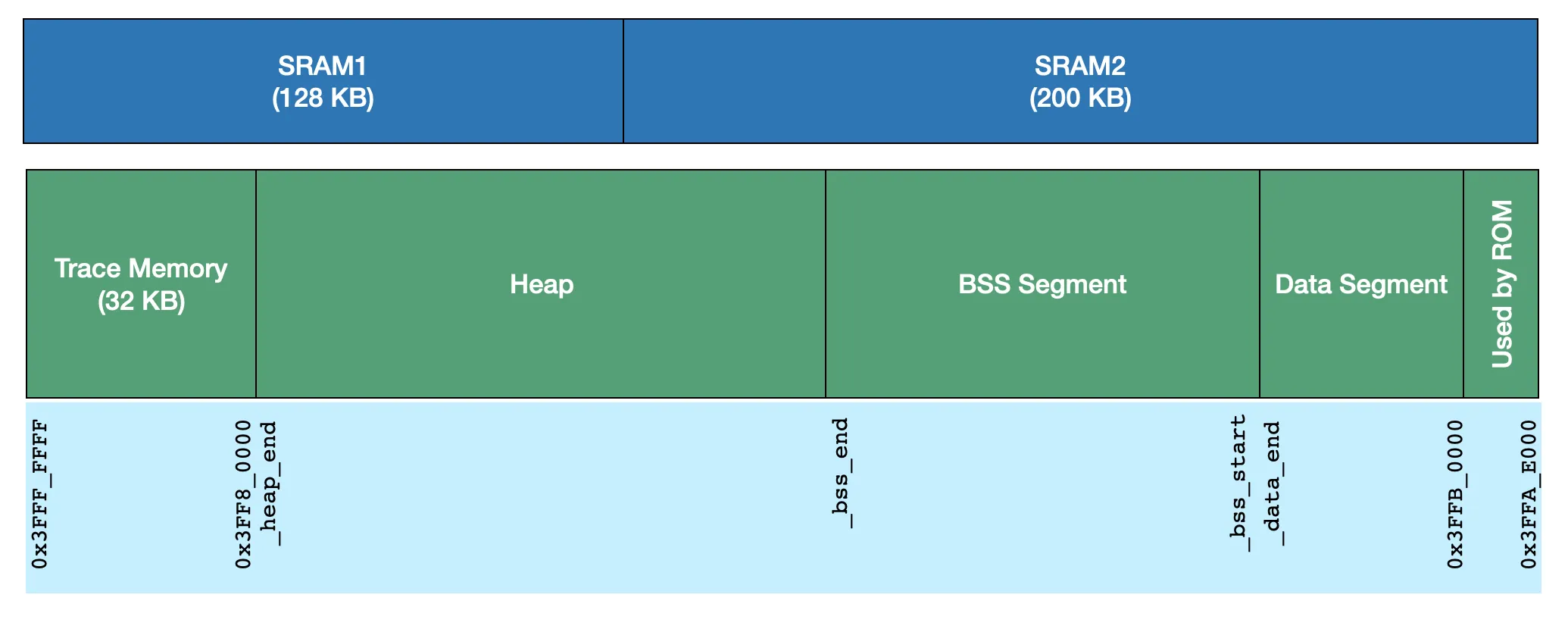
When the application level tracing is enabled, it reserves a fixed 32 KB memory at the end of DRAM. Note that the above diagram shows the layout with BT disabled. But possibly application can use tracing with BT enabled too and in that case BT controller memory will be reserved as well by the linker script.
External SPIRAM#
ESP32 provides an ability to interface optional Pseudo-Static RAM (PSRAM a.k.a SPIRAM) on the same QSPI bus used for the flash using a different chip-select. This memory is directly addressable and just like flash, the accesses to this memory go through cache that is part of IRAM. ESP32 can map maximum 4MB SPIRAM at a time in its address space in the range 0x3F80_0000 to 0x3FBF_FFFF. There are three ways for the application to make use of the SPIRAM
While this allows application to use additional memory, there are certain restrictions on the use of SPIRAM
These ways of using SPIRAM and restrictions on using it are documented in detail here.
Heap Allocator#
From the above diagrams for IRAM and DRAM memory layout you can see that DRAM area _bss_end to 0x3FFF_FFFF (or _heap_end in case of trace memory enabled) and IRAM area _iram_text_end to 0x4009_FFFF are unused memory segment. If SPIRAM is available in the system, that too has unused memory. The application and SDK components always need to allocate and free the memory on demand. So a general purpose memory allocator — a.k.a. Heap Allocator operates on the available free memory and provides memory allocation and freeing APIs for them.
As you see, the memory regions under the heap allocator’s control have different capabilities and access properties. Hence ESP-IDF implements a capability based heap allocator where the caller can specify the purpose of allocation along with the size of allocation. For example, an application may ask for memory specifically that is capable of DMA for using it with some peripheral or it may as memory explicitly from external SPIRAM for audio buffers for which allocating from internal DRAM is not preferred.
ESP-IDF also performs generic malloc and free APIs above the heap allocator’s capability based allocation APIs to make the application porting easy from POSIX type systems. The application configuration can have governing rules to prefer the use of certain memory segment for malloc API based on allocation size.
Using IRAM for Data#
Starting with ESP-IDF release 4.2, we have added an ability to use IRAM for data. As mentioned above, IRAM has access limitations in terms of alignment of address and size. If an unaligned access is made, it results into an exception. The ESP-IDF, after release 4.2, handles these exceptions transparently to provide load/store as desired by the caller. As these unaligned accesses result in exception, the access is slower than the DRAM access. Typically each exception handling requires approximately 167 CPU cycles (i.e. 0.7 usec per access at 240 MHz or 1 usec per access at 160 MHz). The application or SDK components can use the IRAM for data either for BSS at link time or through heap allocator at run time. There are two limitations in using IRAM for data:
ESP-IDF 4.2 provides some ready-made configurations to make effective use of unused IRAM for data such as TLS transmit and receive fragments in single-core mode.
Please checkout this blog for a case-study for memory analysis of an AWS-IoT client application and some common optimisation techniques.
In the next blog, we’ll see more details about how Wi-Fi subsystem and BT subsystem use the memory so that memory availability for the application can be determined. We’ll also see various common use-cases and their memory consumption and possible optimisations for these use-cases. Please stay tuned.