
In this post we will discuss the design and internal workings of Over-The-Air (OTA) Updates framework in ESP-IDF.
We shall also cover some of the features from OTA updates, focused around reliability and security that can help to build better IoT products with ESP32.
Background Information#
Lets cover some basic information essential for understanding the overall OTA update procedure.
Partition Table & Flash Layout#
The Partition table defines the flash layout on ESP32. Applications can specify its desired flash layout using simple CSV files. A template looks like below:
# Name,   Type, SubType, Offset,   Size, Flags
# Note: if you have increased the bootloader size, make sure to update the offsets to avoid overlap
nvs,      data, nvs,     ,        0x4000,
otadata,  data, ota,     ,        0x2000,
phy_init, data, phy,     ,        0x1000,
ota_0,    app,  ota_0,   ,        1M,
ota_1,    app,  ota_1,   ,        1M,
Important points to note:
- A binary partition table image is generated using the above CSV file. This occupies 4KiB (single flash sector) and is located at offset 0x9000 in default configuration. First 8 sectors (32KiB), before this, are reserved for the bootloader image.
- If more space is desired for bootloader, then the partition table offset can be adjusted using configuration option CONFIG_PARTITION_TABLE_OFFSET.
- Partitions ota_0 and ota_1 denote active and passive versions for application firmware. Identical copies ensure power safety during OTA updates.
- Application image partitions (ota_0/ota_1) are always adjusted to align on 64 KiB boundary, as that is the page size for flash cache mapping.
- Even though factory partition is supported, we will not be considering it, as that partition is not supported in anti-rollback scheme. If required, that logic can be coupled in primary firmware itself.
- For simplicity we will also not consider multiple firmware partitions (total 16) even though they are supported in ESP-IDF.
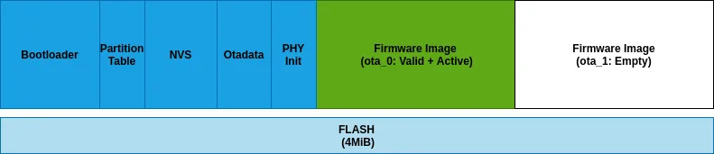
Visual representation of above configuration for 4MiB flash part is shown below:
Application Image Format#
A detailed documentation can be found here , whereas, here we will only consider interesting bits that are applicable for this discussion.
Following is the application image descriptor (present at offset 0x20 in application image):
typedef struct {
    uint32_t magic_word;        /*!< Magic word ESP_APP_DESC_MAGIC_WORD */
    uint32_t secure_version;    /*!< Secure version */
    uint32_t reserv1[2];        /*!< reserv1 */
    char version[32];           /*!< Application version */
    char project_name[32];      /*!< Project name */
    char time[16];              /*!< Compile time */
    char date[16];              /*!< Compile date*/
    char idf_ver[32];           /*!< Version IDF */
    uint8_t app_elf_sha256[32]; /*!< sha256 of elf file */
    uint32_t reserv2[20];       /*!< reserv2 */
} esp_app_desc_t;
Few important fields to note:
- version: Firmware version embedded in image. This can be embedded in firmware image using multiple methods including configuration option or version file. By default its retrieved using command git describe –always –tags command if application is hosted in a git repository.
- secure_version : Security version embedded in image. This can be embedded using configuration option only. This is desired as it groups firmware images based on fixes against security vulnerabilities (e.g. revoked CA certificate) and thus ensuring security. More on this in followup section on anti-rollback feature.
Software Architecture#
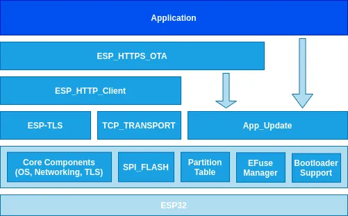
Above is simplified diagram that highlights some key components in an application from ESP-IDF that deals with OTA updates. In most cases, application needs to interact with public interface of esp_https_ota and app_update ____ components only.
- ESP_HTTPS_OTA : This software component provides simplified API for updating device securely over TLS channel. API accepts two mandatory parameters, HTTPS URL where firmware image is hosted and server certificate to validate server’s identity.
- APP_Update : This software component abstracts out the complexity of dealing with partition and flash layer operations. It exposes simplified API that can be directly used by an application for programming firmware to device flash. Additionally it also provides some convenience APIs for dealing with rollback and anti-rollback use-cases that we shall cover in the later part of this article.
HTTPS OTA API#
API for secure OTA update is kept very simple and requires 2 mandatory parameters:
- Server (Firmware) URL
- Server Certificate
Code snippet is as shown below, assuming firmware image is hosted on github.com server:
esp_http_client_config_t config = {
     .url = "https://raw.githubusercontent.com/path/to/firmware",
     .cert_pem = (char *) github_server_start_pem,
};esp_err_t ret = esp_https_ota(&config);
if (ret == ESP_OK) {
     esp_restart();
}
There is also support for advanced APIs which provide more granular control to the application in terms of validation of firmware version, monitoring OTA update progress etc.Detailed documentation for this can be found here.
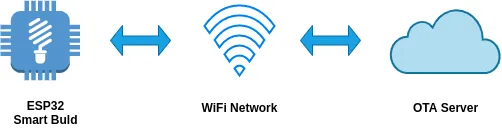
OTA Update Workflow#
Simplified workflow for OTA update looks like below:

- Server authentication ensures that firmware is downloaded from trusted entity.
- Based on version information in downloaded image header, device can decide to perform upgrade.
- Validation on device side includes header and integrity (SHA256 checksum) related checks. This happens after entire firmware image is written to flash partition.
- If hardware secure boot is enabled then firmware image has signature appended to it. For flash encryption cases, it is entirely handled on device level during flash write stage. More on this in later section.
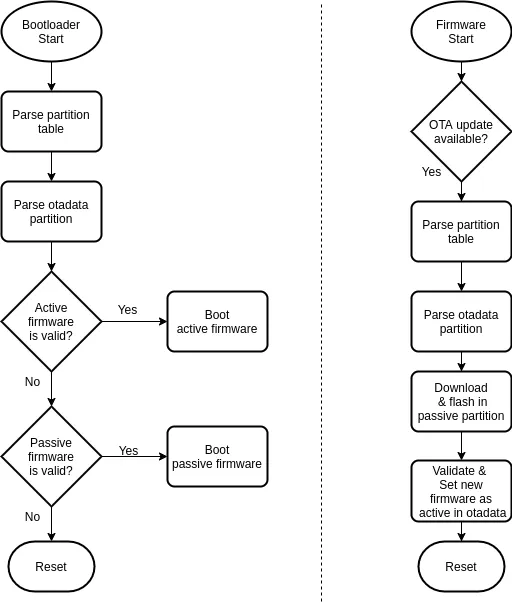
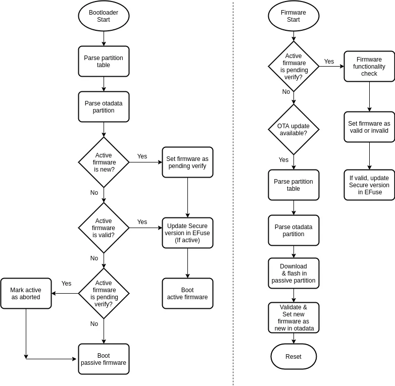
Boot-loader & Application Flowchart#
Two entities play an important role in OTA update process, the boot-loader and the application.
- The boot-loader and application both rely on the partition table to extract information on various partitions and their offsets in flash.
- Partition otadata is responsible for selection of active firmware (latest updated) based on sequence numbers stored within it.
- otadata partition is allocated with 2 flash sectors (similar to active/passive firmware, 8KiB size) and thus allows for power safety while updating sequence numbers and other parameters during OTA update.
Following is a simplified flowchart for decision making involved during OTA update in an application. Also it shows how boot-loader picks up newly updated firmware after OTA update.
Flash Layout Transition#
For normal OTA update scenario, flash layout transition is rather simple. It goes through following stages:
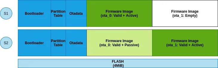
Stage 1#
Newly shipped smart light bulb would have functional ota_0 partition and empty ota_1 partition. Boot-loader will always give control to firmware in ota_0 partition.
Stage 2#
Application after performing OTA update will make ota_1 partition as active by updating its sequence number in otadata partition. Thus from subsequent RESET, boot-loader will always give control to firmware in ota_1 partition (till next OTA update).
Limitations#
In the above scenario, if there is some issue (e.g. early firmware bootup crash) in the newly updated firmware from partition ota_1, there is no way the device can fallback to previous known working firmware.
Consideration I — Rollback#
Typically OTA updates are staged and well tested in actual deployment scenarios, e.g. friend-family devices, beta-users and then finally to larger device groups. However this still can not ensure 100% recovery if OTA update goes wrong due to many parameters like variation in hardware attributes of device, or some rare firmware crashes.
The firmware rollback feature provides an ability to rollback to the previous known working firmware.
Boot-loader & Application Flowchart#
- Unlike normal OTA update workflow, rollback case involves few intermittent states before marking firmware as valid.
- Transition from new firmware to valid or invalid is handled by both application and boot-loader.
Flash Layout Transition#
For rollback enabled OTA update scenario, flash layout transition goes through following stages:
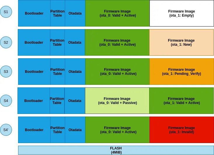
Stage 1#
Newly shipped smart light bulb would have functional ota_0 partition and empty ota_1 partition. Boot-loader will always give control to firmware in ota_0 partition.
Stage 2#
First OTA update writes new firmware image in passive partition (ota_1) and marks its state as ESP_OTA_IMG_NEW . The state is stored in otadata partition along with its sequence number.
Stage 3#
After RESET, boot-loader sees a new firmware with state__ESP_OTA_IMG_NEW__ and turns its state to ESP_IMAGE_PENDING_VERIFY ,____ as its functionality is yet to be validated.
Stage 4/4'#
Once new firmware starts execution, it can set its state to either ESP_OTA_IMG_VALID or ESP_OTA_IMG_INVALID based on application logic (will come to that in next section). If it fails to update the state of new and first time executing firmware then on subsequent RESET, boot-loader updates its state to ESP_OTA_IMG_ABORTED and thus falls back to previous firmware. Following APIs are provided for state transitions:
// Mark firmware as valid and cancel rollback process
esp_ota_mark_app_valid_cancel_rollback();// Mark firmware as invalid and rollback to previous firmware
esp_ota_mark_app_invalid_rollback_and_reboot();
Firmware Functionality#
Lets discuss more on transition to “Stage 4 ” from above.
Firmware functionality can be decided based on various checkpoints within it.
- Successful initialisation
- Connection to WiFi network
- Connection to OTA server
Connection to OTA server being the best possible option, as it ensures possibility of next OTA update. However this may need some changes on cloud agent side as well, which can acknowledge communication from device firmware. Once firmware reaches to desired checkpoint successfully, it can invoke earlier mentioned API to cancel rollback process and continue further execution.
Note: Rollback feature can be enabled through config option, which is discussed in more detail in followup section through working example code.
Consideration II — Anti-Rollback#
Rollback offers an ability to go back to previous working firmware but sometimes this may not be a desired operation. Many times, a device firmware update can also modify some secure credentials (e.g. server’s certificate) embedded within it. This implies that all older firmware images are pretty much obsolete and if executed may posses security risks. “Firmware Anti-rollback ” feature can help to mitigate such issues.
Anti-rollback is a feature that allows to execute firmware only-if the____ security version embedded within it is greater than the one programmed in the device’s EFuse (one-time-programmable memory). Certain bits (up-to 32) can be reserved to store the security version in EFuse. It is ensured that this is kept in sync with the one embedded in the firmware image by both the application and boot-loader during startup.
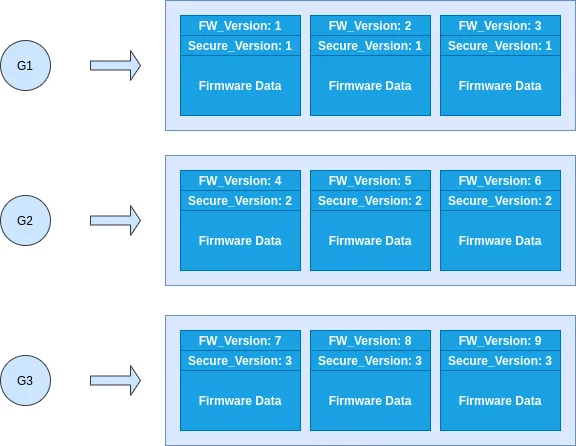
Above image illustrates idea of grouping firmware based on their security versions.
- Each group (G1/G2/G3) has 3 firmware images with different firmware version but same security version.
- If device anti-rollback reserved EFuse has 2 bits set (which means security version 2) then only firmware from G2 and G3 groups will be allowed to execute on device. Firmware images from group G1 having lesser security version will not be allowed to boot.
- Anti-rollback is tightly coupled with rollback, as in version in EFuse is only updated after functionality of new firmware image is confirmed. This can be seen in “Simplified rollback OTA update flowchart” shown earlier.
Working Example in ESP-IDF#
Working example which implements rollback and anti-rollback features can be found here . This is slightly modified version of advanced_https_ota example from ESP-IDF.
Configuration Changes#
Updated sdkconfig.defaults file looks like below:
# Use custom partition table without factory partition
CONFIG_PARTITION_TABLE_CUSTOM=y
CONFIG_PARTITION_TABLE_CUSTOM_FILENAME="partitions_example.csv"# Enable firmware versioning from config option CONFIG_APP_PROJECT_VER_FROM_CONFIG=y
CONFIG_APP_PROJECT_VER="1"# Enable firmware rollback and anti-rollback features
CONFIG_BOOTLOADER_APP_ROLLBACK_ENABLE=y
CONFIG_BOOTLOADER_APP_ANTI_ROLLBACK=y# Set initial secure version to 0 CONFIG_BOOTLOADER_APP_SECURE_VERSION=0# Set secure version eFuse field size CONFIG_BOOTLOADER_APP_SEC_VER_SIZE_EFUSE_FIELD=32# Emulate secure version through flash partition for testing CONFIG_BOOTLOADER_EFUSE_SECURE_VERSION_EMULATE=y
- Both version and secure_version fields in the firmware image are set through config options itself.
- For testing purpose, we have enabled an option to emulate anti-rollback EFuses through flash partition. For actual product deployment scenario this option should be disabled.
Code Changes#
- We have used information from API esp_https_ota_get_img_desc() to decide if OTA update is really required or not. This API retrieves image descriptor part thus its useful to get metadata that involves firmware version and security version. This also prevent further image download from remote server and unnecessary flash program cycles.
- Important point to note is that we are considering successful Wi-Fi connection as a checkpoint within firmware to cancel rollback process and mark image as valid.
- Same API (esp_ota_mark_app_valid_cancel_rollback) is also responsible for updating security version in EFuse matching with current firmware header.
Consideration III — Secure Boot & Flash Encryption#
In this section we will see how OTA updates can be coupled with platform security features (more information covered here) in ESP32.
- Secure boot allows only trusted firmware to execute by verifying its signature with public key on device.
- During an OTA update, the firmware image hosted on the server should be signed with ECDSA NIST256p (secure boot v1 scheme) or RSA-3072 (secure boot v2 scheme) based private key. Signature is calculated on SHA256 checksum of firmware image, offering constant time verification, and then it is appended to it.
- As mentioned earlier in the flowchart diagram, the OTA workflow on application side includes image validation stage. For non secure boot enabled cases, validation includes only integrity checks in the form of image header magic bytes and plain SHA256 checksum. For secure boot enabled cases, it involves verification of signature using public key stored in device.
- After the secure boot verification stage, the firmware is marked as valid (non-rollback case) or new (rollback case). If signature is found to be invalid, its marked as invalid right away aborting the OTA update procedure.
- For flash encryption case there are no additional steps are required on server or device side. Firmware image hosted on the server is still in plain text format with (optional) secure boot signature appended to it. During flash write stage on the device, if flash encryption is enabled then firmware gets written in encrypted manner using hardware AES engine and key from EFuse.
Important Notes#
- Above discussed features like “rollback” and “anti-rollback” must be enabled before device ships out of factory. Since these features enable certain code path in bootloader, which in itself can not be updated on-field.
- It is recommended that any sort of power save modes (e.g. WiFi modem sleep) should be disabled during OTA update. This allows optimal throughput for data transfer. ESP-IDF provided examples take explicit care for this.
- During OTA update flash goes through programming operations (erase/write) and hence flash cache stays disabled. If there are any interrupts that are required to kept enabled, then they should be registered with their handler in internal code memory (IRAM). More information on this can be found here.
Getting robust OTA update for IoT product is very essential and some of the considerations mentioned above can be helpful in making right design decisions!