
Analyze addressable LED frames with Saleae Logic 2#
This optional exercise connects an external instrument to the agent. You will use the experimental Logic 2 MCP server to capture the addressable RGB LED data signal on GPIO27 of the ESP32-C5-DevKitC-1 and analyze the transmitted LED frames.
The MCP server supports Saleae Logic 8, Logic Pro 8, and Logic Pro 16 devices. Keep the Logic 2 application open while using it.
Step 1: Enable the Logic 2 MCP server#
Open Logic 2 and go to Settings > Automation, then enable MCP Server. By default, the local server listens at:
http://127.0.0.1:10530The server is available only from your computer and does not require credentials.
Step 2: Connect Cursor to Logic 2#
Add the server in Cursor Settings > Tools & MCP, or add this entry to ~/.cursor/mcp.json:
{
  "mcpServers": {
    "logic2": {
      "url": "http://127.0.0.1:10530"
    }
  }
}
Confirm that logic2 is connected and its tools are enabled. Then ask:
List the Saleae logic analyzers I have connected. Exclude simulation devices.The agent should report the model and device ID. If it cannot connect, confirm that Logic 2 is running, the MCP server is enabled, and the URL is correct.
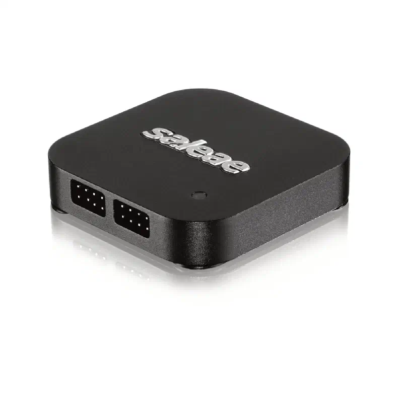
Step 3: Connect the logic analyzer#
Turn off or disconnect the ESP32-C5-DevKitC-1 before attaching probes:
| Signal | ESP32-C5-DevKitC-1 | Saleae |
|---|---|---|
| RGB LED data | GPIO27 | Digital channel 0 |
| Ground | Any GND pin | GND |
- Connect a Saleae ground wire to a GND pin on the board.
- Connect Saleae digital channel 0 to GPIO27.
- Check both connections, then power the board through USB.
The logic analyzer and board must share a common ground. Do not connect a Saleae input to 3V3, 5V, or VBAT. The analyzer input observes the GPIO27 data signal; it does not power the LED.
Step 4: Run the LED application#
Build, flash, and monitor the led-blink project from Assignment 4. Confirm that:
- The project configures the addressable LED data signal on GPIO27.
- The physical RGB LED changes state every 500 ms.
- The monitor reports matching LED ON and OFF transitions.
If you completed the optional colour challenge, note the configured red, green, and blue values. Otherwise, inspect the led_blink implementation and record the values passed to the LED driver while the LED is on.
Step 5: Capture the LED signal#
Addressable LEDs typically use an approximately 800 kHz one-wire signal with sub-microsecond high and low pulses. Use a digital sample rate of at least 10 MS/s; a higher supported rate provides more accurate pulse-width measurements.
Ask the agent to capture GPIO27:
Use the connected Saleae logic analyzer to capture digital channel 0 for
two seconds at a digital sample rate of at least 10 MS/s.
GPIO27 is connected to channel 0 and carries the addressable RGB LED data.
The application updates the LED every 500 ms.
After the capture, identify each burst of activity and the low reset interval
between LED frames. Do not change the firmware.
The capture should show short bursts when the LED state changes, separated by long idle periods.
Step 6: Analyze the LED frames#
Ask the agent to measure and decode one ON frame and one OFF frame:
Analyze one ON frame and one OFF frame from digital channel 0.

1. Measure representative high and low pulse widths.
2. Determine how logical 0 and logical 1 are encoded.
3. Identify the frame reset or latch interval.
4. Decode the 24 data bits sent to the first LED.
5. Determine the channel order from the firmware configuration.
6. Compare the decoded channel values with the RGB values used by the
   led_blink component.

Report measured values separately from protocol assumptions and flag any
timing or decoded value that does not match the firmware.
For many 800 kHz addressable LEDs, each bit lasts approximately 1.25 µs and its value is determined by the high-pulse duration. Exact timing limits and channel order depend on the LED model and driver configuration, so compare the capture with the board documentation and firmware rather than assuming a fixed RGB order.
The OFF frame should contain zero values for all three channels. The ON frame should match the colour configured by the application.
If no frame is visible:
- Check whether channel 0 remains constantly high or low.
- Confirm the probe is connected to GPIO27 rather than an LED power pin.
- Verify the application is updating the physical LED.
- Increase the sample rate if transitions appear too coarse to measure.
- Inspect the raw signal before changing the firmware.
Step 7: Compare software and hardware evidence#
Record:
| Evidence | Result |
|---|---|
| Colour values set by firmware | |
| Decoded ON-frame values | |
| Decoded OFF-frame values | |
| Bit period | |
| Logical 0 high time | |
| Logical 1 high time | |
| Reset/latch low time |
Explain whether the captured frames confirm the firmware logs and visible LED behaviour. If they disagree, identify whether the evidence points to firmware configuration, protocol timing, probe placement, or LED hardware.
Step 8: Clean up#
Stop the monitor and disconnect board power before removing probes. Confirm that no Saleae capture exports or temporary test files were added to the workshop repository.