In this module, you’ll move beyond GPIO to a communication protocol — I2C. You’ll set up an I2C bus, scan for devices, and control GPIO pins through an I/O expander.
I2C Foundations#
What is I2C?#
I2C (Inter-Integrated Circuit) is a two-wire bus protocol for communicating with sensors, displays, and other devices.
The two wires are:
- SDA — Serial Data (bidirectional). Used to propagate data bits.
- SCL — Serial Clock (driven by the controller). Used to synchronize data exchanges on the bus.
Since it’s a bus, multiple devices can share the same two wires. Each device has a unique address (7-bit) that the controller uses to address any device on the bus.
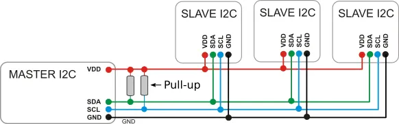
I2C bus architecture with master and slave devices
Theory of Operation#
- Each bus has at least one master and one or more slaves
- The master orchestrates operations on the bus and addresses slaves using the 7-bit address
- Data exchange speed is governed by the clock speed (propagated on SCL)
- A master can perform two operations: read or write
- I2C exchanges data in one-byte chunks
Write Operations#
A master writes data to a slave. You need:
- The address of the slave
- An array of bytes to write
Read Operations#
A master reads data from a slave. You need:
- The address of the slave
- A byte array buffer for the received data
Configurations#
| Setting | Description |
|---|---|
| Clock frequency | 100 kHz (standard), 400 kHz (fast), or custom |
| SDA/SCL pins | Any GPIO with I2C capability |
Exercise A: Bus Scan#
Goal: Set up an I2C bus and scan for connected devices.
1. Create a New Project#
esp-generate --chip esp32c3 -o unstable-hal -o vscode -o esp-backtrace -o log --headless i2c_scan
cd i2c_scan
2. Find an I2C Example#
Navigate to the esp-hal I2C documentation.
Look for an I2C example in:
- The module-level documentation (
esp_hal::i2c) - The
I2cstruct page - The esp-hal examples directory on GitHub
3. Apply the Mental Model#
Read the example and identify:
- Instantiate — How is the
I2ccreated? What peripheral and pins does it need? - Configure — What configuration is applied? (Clock speed, pins)
- Control — What methods are available for reading/writing?
4. Adapt to Your Hardware#
- Check your board’s pinout for the I2C SDA and SCL pins
- Update the pins in the example to match
5. Scan the Bus#
Write a loop that attempts to communicate with every address from 0x01 to 0x7F:
- For each address, try a zero-length write
- If the write succeeds, a device is present at that address
- Print the address of each device found
6. Build and Flash#
cargo build --release
espflash flash target/riscv32imc-unknown-none-elf/release/i2c_scan --monitorExercise B: GPIO over I2C#
Goal: Use the TCA6424A I/O expander to control GPIO pins over I2C, replicating what you did with direct GPIO.
Background#
The TCA6424A is a 24-bit I/O expander connected via I2C. It provides three banks (ports) of 8 GPIO pins each (P0, P1, P2), giving you 24 additional GPIO pins over just two I2C wires.
How I2C Communication Works with the TCA6424A#
Communication happens in two cycles:
- First cycle (write): Send the register address — tells the device which internal register to access
- Second cycle (read or write): Write a value to that register or read back the current value
For a write operation, send the register address followed by the data byte in the same I2C write transaction.
For a read operation, first write the register address, then perform a separate I2C read.
TCA6424A Register Map#
| Register | Port 0 | Port 1 | Port 2 | Purpose |
|---|---|---|---|---|
| Input | 0x00 | 0x01 | 0x02 | Read pin levels |
| Output | 0x04 | 0x05 | 0x06 | Set output pin levels |
| Configuration | 0x0C | 0x0D | 0x0E | Pin dir: 0=out, 1=in |
Steps#
1. Create a New Project#
esp-generate --chip esp32c3 -o unstable-hal -o vscode -o esp-backtrace -o log --headless i2c_expander
cd i2c_expander
2. Configure Pin Direction#
Write to the Configuration register for the appropriate port. Set the corresponding bit to 0 for output.
3. Set a Pin High#
Write to the Output register for the appropriate port. Set the corresponding bit to 1 for high.
4. Blink an LED#
Combine the above in a loop:
- Configure the port direction as output (once at startup)
- In a loop: set the pin high, delay, set the pin low, delay
5. Build and Flash#
cargo build --release
espflash flash target/riscv32imc-unknown-none-elf/release/i2c_expander --monitor
Exercise C: Adaptation Challenge#
Goal: Read a button input through the I/O expander, controlling an LED entirely over I2C.
Steps#
1. Create a New Project#
esp-generate --chip esp32c3 -o unstable-hal -o vscode -o esp-backtrace -o log --headless i2c_challenge
cd i2c_challenge
2. Configure an Input Pin#
Using the TCA6424 registers:
- Set a pin’s configuration bit to
1(input) - This pin should be connected to a button on your board
3. Read the Button State#
- Read the input register for the relevant bank
- Check the bit corresponding to your input pin
- Detect when the button is pressed
4. Control the LED#
Combine input reading with output control:
- Read the button state from the I/O expander
- When pressed, turn on the LED (on the I/O expander)
- When released, turn off the LED
5. Build and Flash#
cargo build --release
espflash flash target/riscv32imc-unknown-none-elf/release/i2c_challenge --monitorCross-HAL Comparison#
How do other HALs handle I2C? Navigate the documentation for these two libraries:
Compare how each HAL handles Instantiate, Configure, and Control for I2C.