
The ESP32-C5 and ESP-SensairShuttle#
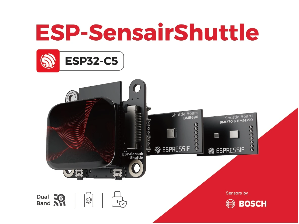
The ESP-SensairShuttle is a sensing development board from Espressif and Bosch Sensortec. An ESP32-C5 module runs your firmware, reads sensors on a plug-in daughterboard, and can drive the optional LCD and audio connectors on the mainboard.
For this workshop you need the mainboard, a ShuttleBoard-BMI270 & BMM350 daughterboard, a USB-C cable that carries data, and a computer with ESP-IDF.
ESP32-C5 in this workshop#
The board mounts ESP32-C5-WROOM-1-N16R8: 16 MB flash, 8 MB PSRAM, and a PCB antenna. The SoC is a 32-bit RISC-V device (HP core up to 240 MHz) with 384 KB on-chip SRAM, optional LP RISC-V core for low-power tasks, and support for external flash and PSRAM through the module.
Wireless stacks (Wi-Fi 6 on 2.4 and 5 GHz, Bluetooth 5 LE, Thread/Zigbee) matter for connected products, but the gesture exercise is fully on-device: the ESP32-C5 collects gyro samples over I²C, runs TensorFlow Lite Micro inference, and prints results on the serial console. The extra PSRAM and flash headroom make it practical to link ESP-TFLite-Micro, sensor drivers, and application code in one ESP-IDF project without tight memory tuning.
| Resource | On ESP-SensairShuttle | Relevance to gesture ML |
|---|---|---|
| Flash | 16 MB (module) | Application, model weights, ESP-IDF components |
| PSRAM | 8 MB (module) | Larger buffers and framework overhead |
| CPU | RISC-V @ up to 240 MHz | Inference and 200 Hz sensor polling |
| Peripherals | I²C, SPI, UART, USB, GPIO | I²C to BMI270; USB-C for flash and monitor |
See the ESP32-C5 datasheet and ESP32-C5-WROOM-1 datasheet for full electrical and memory details.
ESP-SensairShuttle mainboard#
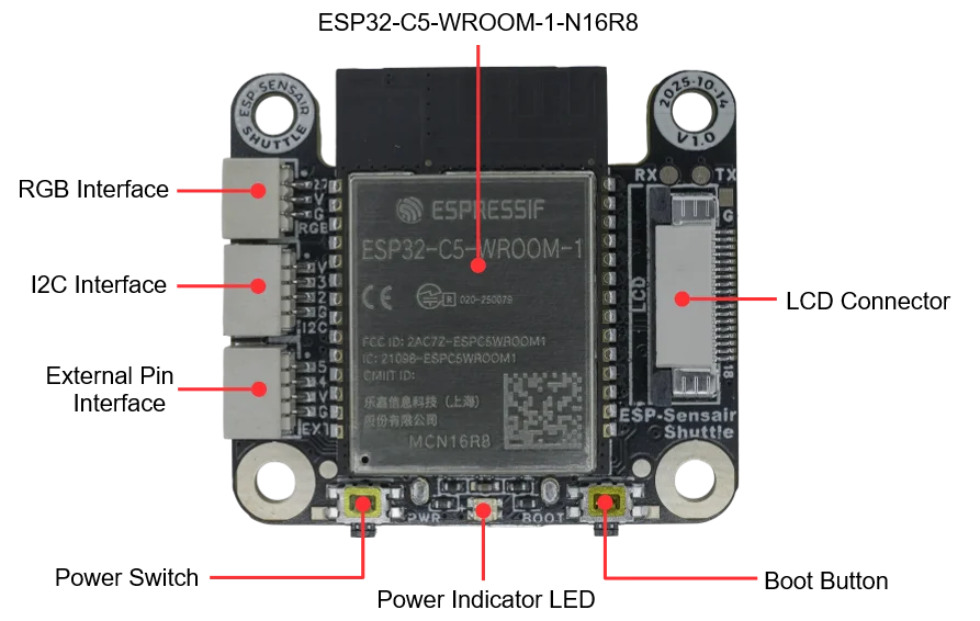
The mainboard hosts the module, power and USB, a Shuttle Board 3.0 connector, an LCD FPC, expansion headers, and battery or audio connectors you can ignore during the gesture labs.
Parts you use in the workshop#
| Label / feature | Role |
|---|---|
| Type-C (USB-C) | Powers the board, provides the USB serial/JTAG link for idf.py flash monitor, and charges an optional Li-ion cell. Use a data-capable cable. |
| Boot button | Connected to GPIO28. Hold Boot, tap Reset (or re-plug USB) to enter download mode if automatic reset fails. The gesture example also uses the button for UI actions when a display is attached. |
| Power switch | Toggles board power when running from battery; with USB only, follow the power indicator colors in the user guide. |
| Shuttle Board connector | 9+7 pin, 1.27 mm header for Shuttle Board 3.0 modules. Install the BMI270 + BMM350 daughterboard here with VDD_SENSOR jumper set to 3.3 V (factory default for Espressif shuttle boards). |
| Shuttle voltage header | Selects 3.3 V or 1.8 V for the daughterboard supply. Keep 3.3 V for the boards shipped with this kit. |
Other interfaces (external I²C on GPIO2/GPIO3, RGB on GPIO27, LCD on SPI, microphone and speaker) are not required for the TensorFlow Lite gesture workflow. The reference example can use the 1.83 inch LCD (240 × 284, ST7789) when you build the full firmware; data collection for training often focuses on serial logging.
Official pin and schematic detail: ESP-SensairShuttle v1.0 user guide — Hardware Reference.