
A walkthrough of the ESP32-S31 features#
This lecture covers the ESP32-S31 and the ESP32-S31-Function-CoreBoard-1 before you enable Secure Boot, flash encryption, and the other assignment modules. The SoC offers dual RISC-V cores with Wi-Fi 6, Bluetooth 5.4, IEEE 802.15.4, a Gigabit Ethernet MAC, and security hardware documented in the datasheet and ESP-IDF documentation.
This is a walkthrough, not a TRM chapter. You will see which peripherals matter on the bench, which security blocks the security overview configures, how the ESP32-S31-Function-CoreBoard-1 exposes USB and Ethernet for the labs, and where to open the official docs when you need pin names, etc. The introduction describes how that path fits the rest of the workshop.
Learning objectives#
By the end of this lecture, you should be able to:
- Name the main ESP32-S31 wired and multimedia peripherals compared with earlier ESP32 parts
- List the SoC security blocks that the later assignments use
- Point to the ESP32-S31-Function-CoreBoard-1 connectors used to flash, debug, and run TLS labs
- Choose the right Espressif datasheet, TRM, board guide, or ESP-IDF security page for a given question
System and connectivity#
The ESP32-S31 has a dual-core 32-bit RISC-V CPU at up to 320 MHz, 512 KB internal SRAM, and external PSRAM and flash over high-speed SPI. One core implements 128-bit SIMD for signal-processing style workloads. An MMU maps external memory, which you rely on once flash encryption is enabled and the application grows.
For radios and wired links, the SoC integrates 2.4 GHz Wi-Fi 6 (802.11ax), Bluetooth 5.4 (LE and Classic), IEEE 802.15.4 (Thread and Zigbee), and a Gigabit Ethernet MAC. On the ESP32-S31-Function-CoreBoard-1, the RJ45 port is an easy choice for TLS when you want a fixed wired lab network instead of Wi-Fi credentials in a classroom.
New peripherals on the ESP32-S31#
If you have used ESP32-S3 or ESP32-C SoCs, the I/O list will look familiar but longer. The ESP32-S31 has 60 programmable GPIOs, multiple UART/SPI/I2C blocks (including low-power variants), USB 2.0 High-Speed OTG, USB Serial/JTAG, TWAI (CAN FD), SDIO, timers, ADCs, touch sensing, and motor-control PWM.
For display and audio products, the same SoC adds a JPEG codec, Pixel Processing Accelerator (PPA), 2D-DMA, camera and LCD controllers, and I2S with hardware Bluetooth audio timing. The security assignments ignore most of that, but it matches the ESP32-S31-Function-CoreBoard-1 layout: Ethernet, USB host, microphone, and speaker for connected voice demos.
The table below ties SoC interfaces to this workshop:
| Area | ESP32-S31 capability | Relevance in this workshop |
|---|---|---|
| USB | USB 2.0 HS OTG + USB Serial/JTAG | Flashing, debug, and optional device-mode workflows |
| Ethernet | 1000 Mbps MAC (with external PHY on the board) | TLS over a stable wired link in Assignment 1 |
| Wireless | Wi-Fi 6, Bluetooth 5.4, 802.15.4 | Wi-Fi path used in Assignments 1 to 5 |
| Storage | External flash and PSRAM | Targets for flash encryption and secure boot |
| Multimedia | JPEG, PPA, I2S, codec-friendly design | Optional product features outside this security lab track |
Security elements (overview)#
The security features overview covers these blocks in detail. The ESP32-S31 includes a cryptography and security component described in the ESP-IDF security overview:
- Secure Boot and flash/PSRAM encryption for authenticity and confidentiality of code and data at rest
- Hardware accelerators (AES, SHA, RSA, ECC, HMAC) and a True Random Number Generator (TRNG) for TLS and provisioning
- Digital signature peripherals (RSA_DS, ECDSA_DS) so private signing material can stay out of normal software reach
- Secure Debug Controller, power-glitch detection, and side-channel hardening on selected blocks
- Access Permission Management (APM) and Trusted Execution Environment (TEE) support for isolating software on multi-app products
The assignments enable these controls one module at a time.
Development kit: ESP32-S31-Function-CoreBoard-1#
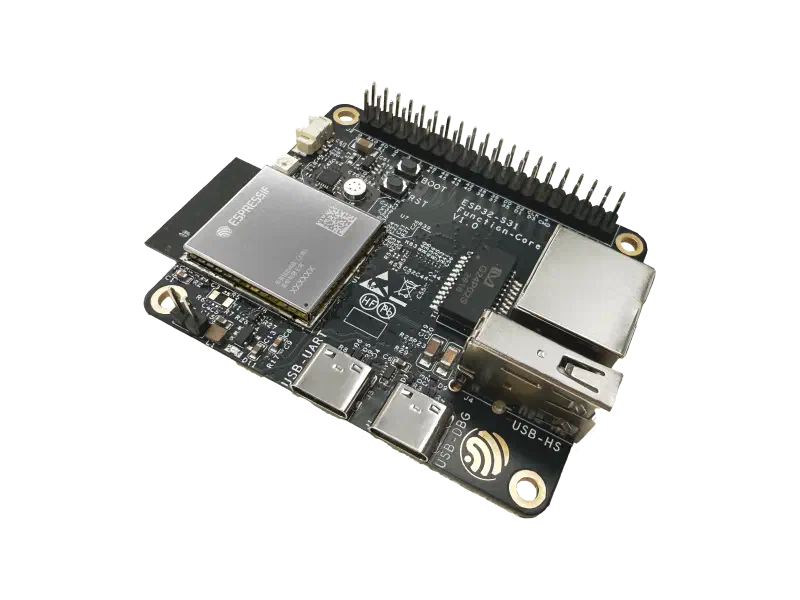
The ESP32-S31-Function-CoreBoard-1 is the board used in this workshop. It carries the ESP32-S31-WROOM-3 module (16 MB flash and 16 MB PSRAM in the mass-production configuration), breaks out GPIOs on header J2, and adds Gigabit Ethernet, two USB-C ports (UART bridge and native USB Serial/JTAG), a USB 2.0 Type-A host port, microphone and speaker paths through an ES8311 codec, an addressable RGB LED, and Boot and Reset buttons.
Power the board from either USB-C port or the 5 V and GND pins on J2. For daily ESP-IDF work, the USB Serial/JTAG port is enough to build, flash, and monitor; the USB-to-UART port is a familiar fallback. Use Ethernet when you want TLS on a fixed lab network.
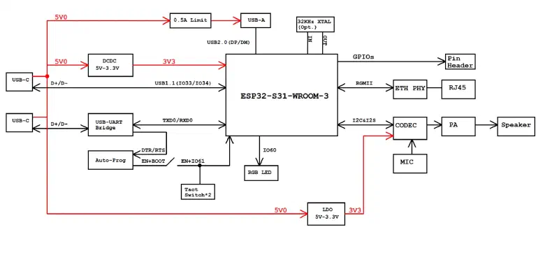
Block diagram#
The diagram below shows how the ESP32-S31-WROOM-3 module connects to USB, Ethernet, and audio on the board.
Board components#
The front of the board contains the interfaces and controls used most often during development:
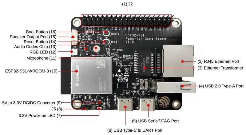
| No. | Component | Description |
|---|---|---|
| 1 | J2 pin header | Exposes power, ground, GPIO, and peripheral signals |
| 2 | RJ45 Ethernet port | Connects the board to an Ethernet network |
| 3 | Ethernet transformer | Provides signal coupling and isolation for Ethernet |
| 4 | USB 2.0 Type-A port | Connects USB peripherals to the board |
| 5 | USB Serial/JTAG port | Native USB connection for flashing, monitoring, and JTAG debugging |
| 6 | USB Type-C to UART port | USB-to-UART connection for flashing and serial monitoring |
| 7 | 3.3 V power-on LED | Indicates that the board’s 3.3 V supply is active |
| 8 | J5 | Current-measurement header; remove the jumper to insert an ammeter in series with the module supply (see the user guide) |
| 9 | 5 V to 3.3 V DC/DC converter | Supplies the board’s 3.3 V power rail |
| 10 | ESP32-S31-WROOM-3 | Module containing the ESP32-S31 SoC |
| 11 | Microphone | Captures audio input |
| 12 | RGB LED | User-controllable status indicator |
| 13 | Audio codec | Converts and routes digital and analog audio |
| 14 | Reset button | Resets the ESP32-S31 |
| 15 | Speaker output port | Connects an external speaker |
| 16 | Boot button | Controls the boot mode and can be used as an input |
The back of the board contains additional interface circuitry:
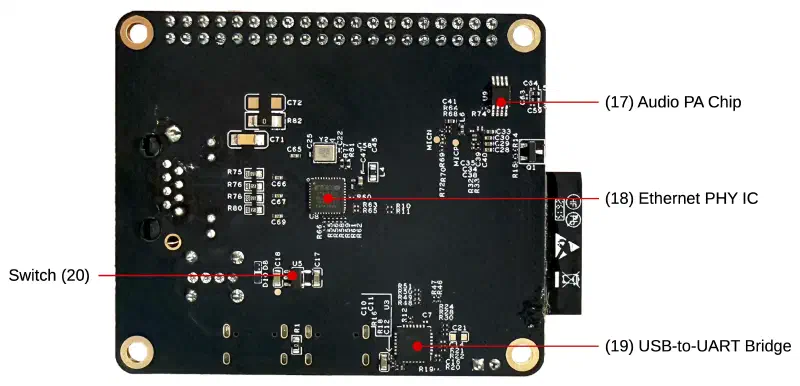
| No. | Component | Description |
|---|---|---|
| 17 | Audio power-amplifier chip | Drives the speaker output |
| 18 | Ethernet PHY | Implements the Ethernet physical layer |
| 19 | USB-to-UART bridge | Converts USB communication to the UART interface |
| 20 | Switch | TPS2051C USB power switch; limits USB host port current to 500 mA |
Software support#
Use ESP-IDF v6.1 with target esp32s31, as listed in the workshop prerequisites. Install and activate the framework with EIM or the ESP-IDF extension for VS Code, then open or create a project and run idf.py --preview set-target esp32s31.
ESP-IDF v6.1 support for the ESP32-S31 is still in preview. APIs, default configurations, and documentation may change between releases. Pin the ESP-IDF version you use for the workshop and read release notes before you ship production firmware.
Espressif also publishes esp_board_manager for the ESP32-S31-Function-CoreBoard-1, which can initialize the codec, LED, and buttons when you move past bare security examples. Secure boot, encryption, and related options still come from ESP-IDF Kconfig, eFuse, and the guides in the next section.
Documentation and resources#
Use these references while you work through the workshop:
| Document | Use it when you need |
|---|---|
| ESP32-S31 Series Datasheet | Feature lists, electrical limits, and security block overview |
| ESP32-S31 Technical Reference Manual | Register-level detail for peripherals and security hardware |
| ESP32-S31-WROOM-3 Datasheet | Module pinout, memory, and antenna information |
| ESP32-S31-Function-CoreBoard-1 user guide | Board setup, connectors, and current measurement |
| ESP32-S31-Function-CoreBoard-1 schematic (PDF) | Net names and power paths for hardware debug |
| ESP-IDF: Security overview (ESP32-S31) | How ESP-IDF maps SoC features to Secure Boot, flash encryption, and identity |
| ESP Hardware Design Guidelines (ESP32-S31) | Product-level integration and layout guidance |
For a first flash and serial connection, follow ESP-IDF Get Started for ESP32-S31.