
The map for your board#
The ESP32-S31-Korvo-1 is a multimedia development board built around the ESP32-S31-WROOM-3 module. It combines the camera, display, touch, audio, local storage, controls, and memory needed to prototype smart audio and vision products.
The installed module has 16 MB flash and 16 MB PSRAM. ESP32-S31-Korvo-1 boards can ship with either a 3-megapixel OV3660 DVP camera, supporting up to 2048 × 1536, or an SC101IOT DVP camera, supporting up to 1280 × 720. The package also includes a 4.3-inch, 800 × 480 LCD subboard. These are the primary peripherals used in this workshop.
Board overview#
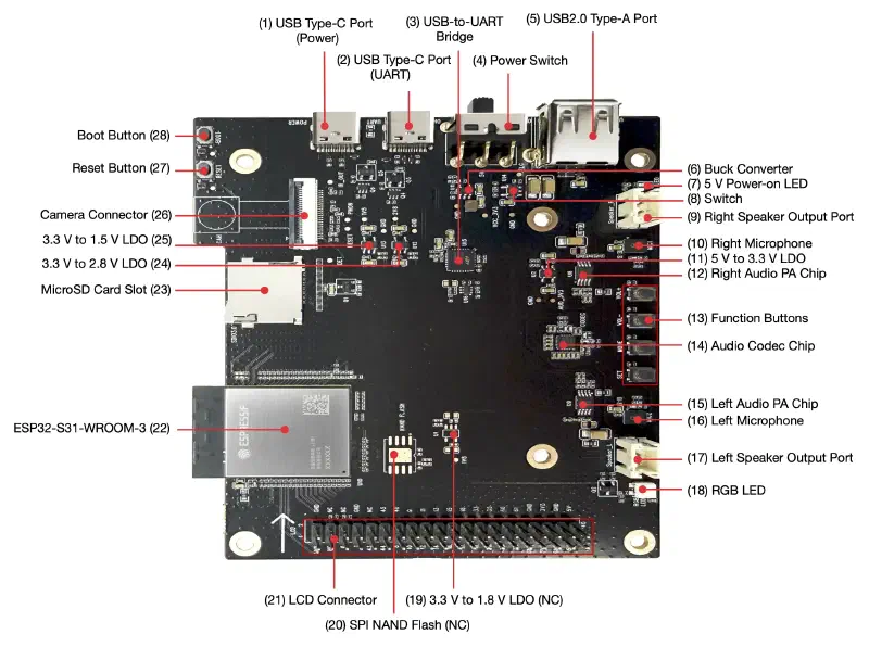
| Hardware | Details | Workshop use |
|---|---|---|
| Module | ESP32-S31-WROOM-3, PCB antenna, 16 MB flash, 16 MB PSRAM | Application, inference, and frame buffers |
| Camera | OV3660 up to 2048 × 1536, or SC101IOT up to 1280 × 720, over an 8-bit DVP interface | Captures face and hand images |
| LCD subboard | 4.3-inch, 800 × 480 parallel RGB display with GT1151 touch | Live camera view and overlays |
| RGB LED | Addressable LED on GPIO37 | Normal and intrusion status |
| Audio | Two analog microphones, ES8389 codec, two 3 W amplifiers | Available for future multimodal applications |
| Controls | PLAY, SET, VOL-, VOL+, Boot, and Reset | User input and recovery |
| Storage | 16 MB module flash plus optional 4-bit microSD, SDIO 3.0 capable | Stores scripts and models; microSD is reserved for large model files |
| USB | Type-C power, Type-C UART, and Type-A USB 2.0 Host | Power, flashing, logs, and USB devices |
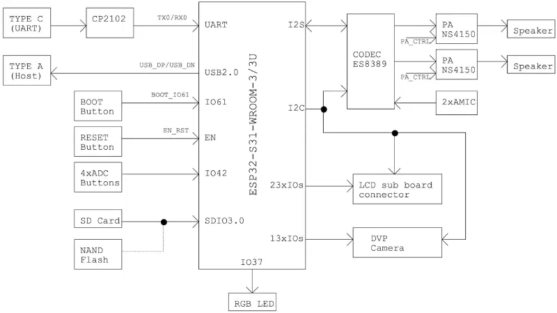
Block diagram#
Camera and display#
The OV3660 and SC101IOT send pixels to the ESP32-S31 through eight parallel data signals plus pixel clock, frame synchronization, and line synchronization. ESP-Vision registers the installed camera as a V4L2-compatible video device through esp_video. The default camera configuration enables both sensors so esp_video can auto-detect the populated module at runtime.
The OV3660 supports resolutions up to 2048 × 1536, while the SC101IOT supports up to 1280 × 720. Workshop applications use lower frame sizes to reduce frame-buffer size and processing load for live display and inference.
The camera is mounted with a 180-degree board rotation. Applications that render the frame should account for this orientation when processing or displaying an image.
The LCD subboard uses a 16-bit parallel RGB data bus. Its GT1151 touch controller communicates over I2C. ESP-Vision provides APIs for displaying camera frames and graphics on the LCD without requiring you to configure these interfaces.
This division is important:
- The camera driver produces frames.
- The PPA can scale or rotate frames.
- ESP-DL performs inference.
- LVGL renders the frame and annotations.
Audio, controls, and storage#
The dual analog microphones and left/right speaker outputs connect through the ES8389 codec. Audio samples use TDM over I2S; codec control uses I2C. Each speaker output can drive a 4 Ω, 3 W speaker through an NS4150B amplifier.
The ESP32-S31 MCLK signal is not connected on this board. The board documentation recommends a 16 kHz audio sampling rate.
The four function buttons share an ADC input through a resistor divider. Each button produces a different voltage level that software can identify through a single ADC channel.
The RGB LED is a WS2812-compatible addressable LED controlled by GPIO37. It requires a color value rather than a simple high/low GPIO level.
The microSD slot uses the SDIO interface by default. Its GPIOs are shared with an unpopulated SPI NAND footprint, so both interfaces cannot be used simultaneously without hardware rework.
Power, USB, and flashing#
The board has two USB Type-C connectors:
| Connector | Power | Data |
|---|---|---|
| Power | Yes | No |
| UART | Yes | USB-to-UART flashing and serial logs |
The USB Type-A connector is connected to the ESP32-S31 USB 2.0 High-Speed OTG peripheral and can supply up to 500 mA in Host mode.
When the USB Type-A connector is used in device mode with a Type-A to Type-A cable, it can also power the board. This supply bypasses the board’s power switch, so moving the switch to OFF does not turn the board off. Disconnect the Type-A cable to fully remove power.
Automatic download normally uses the USB-to-UART bridge. If automatic download fails:
- Hold Boot.
- Press and release Reset.
- Release Boot.
- Retry the flash command.
Resources#
What you learned#
In this overview, you learned:
- Which ESP32-S31-Korvo-1 peripherals support the vision exercises
- How the camera, display, touch controller, LED, audio codec, and microSD card connect to the SoC
- Which USB connector carries flashing and serial data
- How ESP-Vision simplifies access to the board’s camera and display